DIRECTION 5750007-1EN, REV. 1 LOGIQ E10 BASIC SERVICE MANUAL
Chapter 8 Replacement Procedures 8 - 343
Light Block (Hard Drive/Network Status) replacement
Table 8-355 Light Block (Hard Drive/Network Status) replacement
Steps Corresponding Graphic
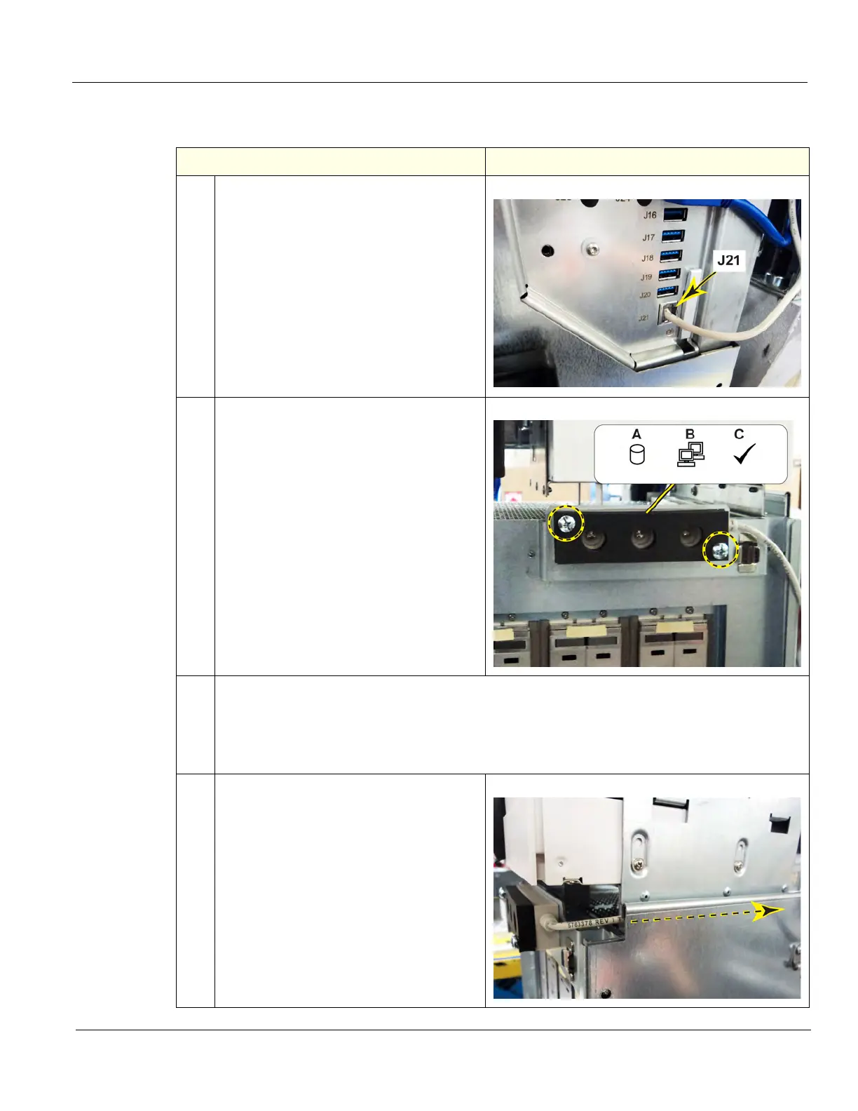
1.
Disconnect the Module cable from J21 of
the ECB
2.
The Module is located on the front, top,
right side of the Card Cage.
Remove the two Phillips screws securing
the Module and foam seal to the Card
Cage, using a #2 Phillips screwdriver. DO
NOT discard the screws or seal.
A = Hard Drive
B = Network
C = Blue - 1 GB Network Okay
White - GB Network (slow)
3.
Install the replacement Module and the foam seal. Tighten the screws securely, they will bottom
out when they are installed.
The seal will not be tight against the Module. It is intentional for the seal to be loose. The seal
will be pressed against the Card Cage and Front cover to capture the light activity and direct it
through the Front Cover.
4.
Route the Module cable along the Card
Cage, as shown and around the back of the
Card Cage to J21 on the ECB.
Connect the cable to J21 on the ECB.

 Loading...


