EasyManua.ls Logo

GE MAC 2000 Service Manual

GE MAC 2000
184 pages
To Next Page IconTo Next Page
To Previous Page IconTo Previous Page
Page #18 background image
Introduction
Whenusingstainlesssteelorsilverelectrodes,adebrillatordischargecurrentmay
causetheelectrodestoretainaresidualchargecausingapolarizationorDCoffset
voltage.ThiselectrodepolarizationblocksacquisitionoftheECGsignal.Toavoidthis
condition,ifthereisasituationwhereadebrillationproceduremightbenecessary,
usenon-polarizingelectrodes(whichdonotformaDCoffsetvoltagewhensubjected
toaDCcurrent)suchassilver/silver-chloridetypes.
Ifyouusepolarizingelectrodes,GEHealthcarerecommendsdisconnectingthe
leadwiresfromthepatientbeforedeliveringtheshock.
ElectrodedebrillationrecoveryistheabilityoftheelectrodetoallowtheECGtraceto
returnafterdebrillation.GEHealthcarerecommendsusingnon-polarizingdisposable
electrodeswithdebrillationrecoveryratingsasspeciedinAAMIEC125.2.2.4.AAMI
EC12requiresthatthepolarizationpotentialofanelectrodepairdoesnotexceed100
mV5secondsafteradebrillationdischarge.
Refertothesuppliesandaccessoriesreferenceguideforthissystemforalistof
approvedelectrodes.
AccuracyofInputSignalReproduction
OverallSystemErrormeetsAAMIEC113.2.7.1requirements.OverallSystemErroris
betweenorwithin±5%or±40µV,whicheverisgreater.
FrequencyResponsemeetsAAMIEC113.2.7.2requirements,usingtestingmethods
AandD.Frequencyresponseisbetweenorwithin±10%between0.67and40Hz
andbetween+0and-10%for20ms,1.5mVtriangularinput.
ModulatingEffectsinDigitalSystems
Thisdeviceusesdigitalsamplingtechniquesthatmayproducesomevariationin
amplitudesofQ,R,and/orSwavesfromoneheartbeattothenext,whichmaybe
particularlynoticeableinpediatricrecordings.Ifyouobservethisphenomenon,
beawarethattheoriginofamplitudevariationsisnotentirelyphysiological.For
measuringvoltagesofQ,R,andSwaves,GEHealthcareadvisesusingtheQRS
complexeswiththelargestdeectionoftheparticularwaves.
EMI/EMC/RFSafetyInformation
Thissystemisdesignedandtestedtocomplywithapplicableregulationsregarding
EMCandmustbeinstalledandputintoserviceaccordingtotheEMCinformation
statedintheElectromagneticCompatibilityappendixoftheServiceand/orOperator’s
manual.ChangesormodicationstothissystemnotexpresslyapprovedbyGE
HealthcarecouldcauseEMCissueswiththisorotherequipment.
Beforeinstallingorusingthedeviceorsystem,beawareoftheproximityofknownRF
sources,suchasthefollowing:
RadioandTVstations
PortableandmobileRFcommunicationdevices(cellphones,two-wayradios)
X-ray,CT,orMRIdevices
18
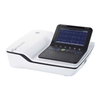
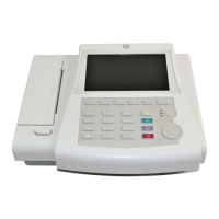
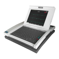
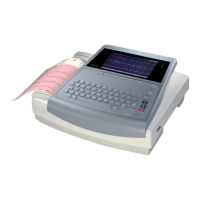
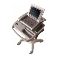
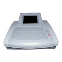
MAC™2000ECGAnalysisSystem
2053535-003C

Table of Contents

Other manuals for GE MAC 2000

Questions and Answers:

GE MAC 2000 Specifications

General IconGeneral
ECG TypeResting ECG
Number of Channels12
Report FormatPDF, XML
Battery TypeRechargeable lithium-ion
ConnectivityEthernet
Data StorageInternal memory
DisplayHigh-resolution color LCD
Power SupplyUniversal AC power supply

Summary

Introduction

Intended User of this Product

Identifies the intended users of the MAC™ 2000 ECG Analysis System for proper operation.

Indications for Use

Outlines the approved applications and medical scenarios for using the MAC™ 2000 ECG Analysis System.

Contraindications

Lists situations where the MAC™ 2000 ECG Analysis System should not be used to ensure patient safety.

Regulatory and Safety Information

Covers essential regulatory compliance, safety standards, and hazard warnings for the device.

Safety Hazards

Details potential dangers like electrical shock, strangulation, explosion, and equipment malfunction.

Classification of Medical Device

Classifies the device according to IEC 60601-1 standards for electrical shock and safety.

Equipment Identification

Explains how to identify the product, including labels for model, serial number, and ratings.

Symbol Descriptions

Explains the meaning of various symbols and icons found on the device and its packaging.

Product Overview

Product Description

Provides a general description of the MAC™ 2000 ECG Analysis System and its capabilities.

Hardware Overview

Details the physical components of the system, including their location and function.

Front View

Illustrates and describes the components visible on the front of the device.

Internal View

Shows and explains the internal components and their arrangement within the system.

Keypads

Describes the standard and stress keypads, including the function of each key.

Architecture and Theory of Operation

Explains the system's block diagram, hardware/firmware architecture, and product interfaces.

Product Interfaces

Details the various input/output ports and connectors available on the system.

Service Setup

Accessing Service Setup

Provides the procedure to enter the device's service mode using a password.

Device Settings

Guides on configuring essential device settings like serial number and keyboard language.

System Diagnostics

Explains how to perform various diagnostic tests to verify system functionality.

Testing the Display

Details the steps to test the display's functionality and pixel integrity.

Checking the Battery Status

Describes how to check the current status and remaining life of the device's battery.

Updating the Software

Provides instructions for updating the system software via an SD card.

Formatting the Flash Memory

Outlines the procedure for formatting the device's flash memory to resolve data corruption.

Maintenance

FRU Replacement Procedures

Introduces procedures for replacing Field Replaceable Units (FRUs) within the system.

Battery

Details the procedure for replacing the device's rechargeable battery pack.

Device Covers

Explains how to remove and replace the top cover, chassis, and bottom cover of the device.

Chassis

Covers the procedures for detaching and attaching the main chassis of the system.

Printer

Describes how to remove and replace the printer module assembly and its components.

Printer Motor and Gear Assembly

Details the steps for replacing the printer motor and associated gears.

Printhead

Details how to clean, remove, and replace the printer's printhead.

Printer Door

Explains the procedure for removing and replacing the printer door.

Display Assembly

Explains the steps for removing and replacing the system's display assembly.

Keypad

Provides instructions for removing and replacing the device's keypad.

Internal Modem

Details the procedure for removing and replacing the internal modem component.

PWA

Outlines the steps for removing and replacing the Printed Wiring Assembly (PWA).

KISS Pump Assembly (Option)

Describes how to remove and replace the optional KISS Pump Assembly.

Functional Checkout

Details visual inspections and functional checkout procedures after FRU replacement.

Electrical Safety Checks

Guides on performing electrical safety tests, including leakage current and ground continuity.

Troubleshooting

ECG Data Noise

Discusses common causes of ECG signal noise and potential solutions.

General Fault Isolation

Provides a systematic approach to identifying and resolving system faults.

Visual Inspection

Outlines a thorough visual check of the equipment to identify potential problems.

Diagnostic Tests

Explains how to use diagnostic tests to verify system functionality after troubleshooting.

Error Codes

Lists and explains various error codes generated by the system for fault diagnosis.

Acquisition Error Codes

Details specific error codes related to the ECG acquisition module.

Printer Internal Error Codes

Lists and explains error codes related to the printer's internal operations.

Parts List

Part Identification

Helps identify system parts by referencing diagrams and callout numbers.

FRU Lists

Lists all Field Replaceable Units (FRUs) with their part numbers and quantities.

Cover Bottom (2066261-001)

Lists parts included in the Cover Bottom FRU kit.

Printer (2066261-002)

Lists parts included in the Printer FRU kit.

Keypads, Non-Stress

Lists available non-stress keypads and their corresponding part numbers.

Keypads, Stress

Lists available stress keypads and their corresponding part numbers.

Power Supply Cords

Lists various power supply cords with their part numbers.

Related Documents

Documents Related to MAC™ 2000 ECG Analysis System

Lists other GE Healthcare documents relevant to the MAC™ 2000 system.

Documents Available in Other Languages

Provides information on the availability of manuals in different languages.

Electromagnetic Compatibility (EMC)

Guidance and Manufacturer’s Declaration—Electromagnetic Emissions

Declares the system's compliance with electromagnetic emissions standards.

EMC Emissions Test

Presents test results for electromagnetic emissions according to relevant standards.

Guidance and Manufacturer’s Declaration—Electromagnetic Immunity

Declares the system's compliance with electromagnetic immunity standards.

Recommended Separation Distances

Provides guidelines on safe separation distances for RF communication equipment.

Technical Specifications

System Specifications

Lists the general hardware and environmental specifications of the system.

Display

Details the specifications of the device's display screen.

Keypad

Lists the specifications related to the device's keypad.

Printer

Provides the technical specifications for the system's printer.

Electrical

Outlines the electrical requirements and specifications for the device.

Battery

Lists the specifications for the rechargeable battery pack.

Acquisition, Processing, and Performance

Details how the system acquires, processes, and performs ECG data analysis.

Operating Modes, Features, and Options

Describes the various operating modes, features, and optional configurations of the system.

WiFi Country List

Allowable Channels

Lists the allowed wireless channels for WiFi operation by country.

Related product manuals