4. Measuring Thickness
Page 106 DMS 2 Operating Manual
Step 5:
You may now navigate through the micro grid, just
as you would through any data file, storing thickness mea-
surements in each grid location.
Step 6:
To leave the Micro-Grid, quickly press . This will
return the instrument to the test mode, with the next data file
position (not Micro-Grid position) active.
Step 7:
To re-access the micro grid, first return to the data
point where it is stored, then enter the DR mode by pressing
. In the DR mode, press until the RECORD
submenu is selected.
Step 8
: Press below the ITEM selection until ATTACH-
MENT TYPE is highlighted.
Step 9:
Press below the VALUE selection, this will
“open” the micro grid’s navigation window.
Step 10
: Press to return to the Test Mode with the
Micro-Grid open. Proceed with navigating through and storing
data points in the Micro-Grid, as described above.
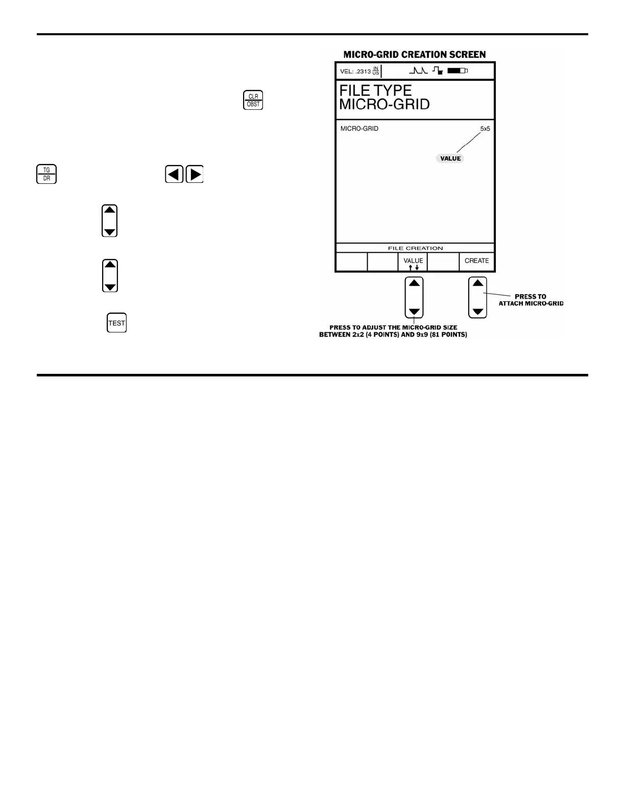
FIGURE 4-7—This is a Micro-Grid creation screen.
 Loading...


