4. Measuring Thickness
Page 114 DMS 2 Operating Manual
• HOLLOW—The A-scan is displayed as a line.
• SOLID—The A-scan’s outer shape remains the same.
The image will be filled in with solid shading (default).
Step 5:
The A-scan appearance will be set to the option last
chosen.
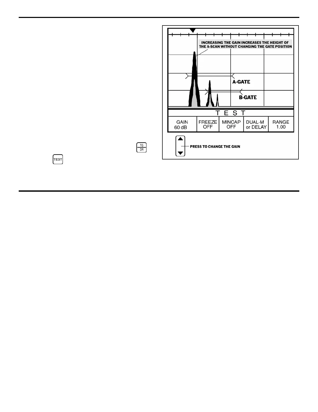
4.4.2 Adjusting the Instrument’s Gain
Adjusting the instrument’s GAIN changes the amplitude
(height) of the displayed A-scan image. Note that the default
GAIN is automatically set when the probe type is specified, or
when a DIALOG-style probe is connected. Under most
situations, this default value will be sufficient. If the instrument’s
gain needs to be modified, follow this procedure. The effect of
increasing and decreasing gain is shown in Figure 4-10. The
gain can be adjusted from most of the submenus in the TG
Primary Menu, as well as from the Test Menu. Note that gain
adjustment is only available in Dual, S-Flank, SIP, TopCOAT,
and Auto-V TG modes.
Step 1:
If necessary, activate the TG Primary Menu or
the Test Menu .
FIGURE 4-10—The height of the A-scan is adjusted with the
GAIN setting. Note that increasing the gain amplifies the
signal and increases the height of the A-scan image.
 Loading...


