1. Getting Started
DMS 2 Operating Manual Page 15
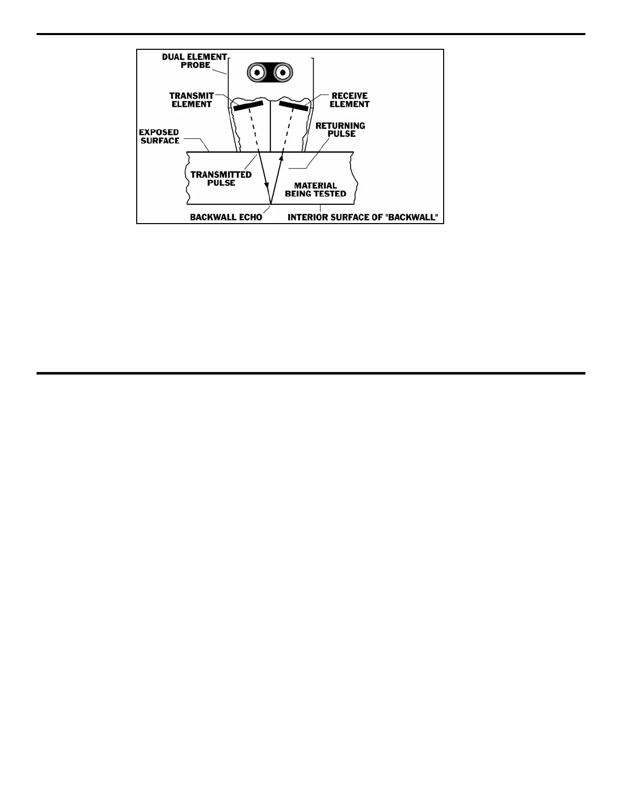
FIGURE 1-9—The operation of a dual-element probe is shown here.
When the DMS 2 is operating in the dual mode, the A-scan
display graphs the amplitude of the actual ultrasonic pulse as
it’s received by the probe. A typical A-scan display is shown in
Figure 1-10. Notice that an A-gate appears in the figure. In the
dual mode, the thickness measurement is calculated based on
the amount of time that passes between the first transmission
of an ultrasonic sound pulse (this first transmitted pulse isn’t
shown on the A-scan display) and the first echo that crosses
this A-gate.
SIP Measurement Mode
The SIP mode uses a single element probe to transmit a sound
pulse into the material being tested. Like the dual mode, the
thickness measurement is calculated based on the time that
passes between the initial pulse and the first echo that crosses
the A-gate.
 Loading...


