GE
D
IRECTION GB091046, REVISION 2 VIVID E9 / VIVID E7 BT’13 SERVICE MANUAL
5 - 66 Section 5-10 - Power distribution
5-10-2-1 General description (cont’d)
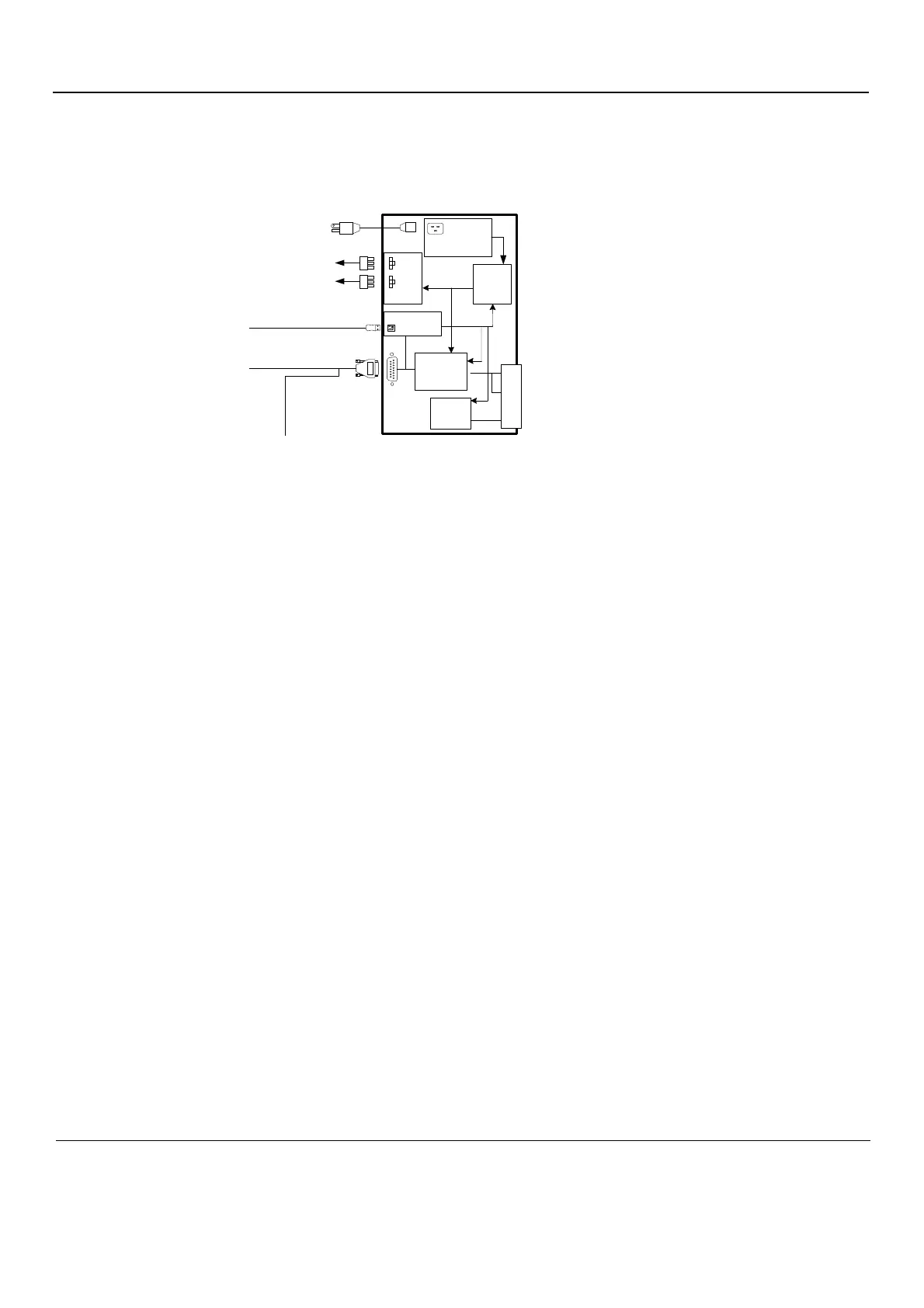
Power from the wall outlet (100 VAC to 230 VAC, 50/60 Hz) is connected to the Main Power Supply.
The Main Power Supply delivers the needed voltages to the rest of the system:
• Internal Peripherals (115 VAC)
• Front End Rack (DC power with several voltages)
- +24 VDC
- +/- 15 VDC
- +11 VDC
-+/-6V VDC
• Front End Rack (TXPSV1 and TXPSV2 for the transmitters)
• Front End Rack (PMXVOUT for the probe channel multiplexers)
• Back End Processor (48 VDC)
• Operator Panel, LCD, XYZ motors (48 VDC)
Figure 5-42 Main Power Supply block diagram
'02725
&175/
+%5,'*(
'&'&
&219(57(56
32:(5
)$&725
&255(&7,21
,62/$7,21
$1'
'&+($'
9$&
,19(57(5
&21752/
0$,132:(56833/<
72
35,17(56
DC VOLTGES -> FEP’S MOTHERBOARD -> FEP’S BOARDS
TX POWER TO FEP MOTHERBOARD TO RELAY CARD
+48 VDC
TO
BEP POWER SUPPLY
TO MOTOR/BRAKE CONTROL
USB FROM BEP
90 - 250 VAC 50/60 Hz MAINS
2 x 115 VAC
 Loading...


