GE
D
IRECTION GB091046, REVISION 2 VIVID E9 / VIVID E7 BT’13 SERVICE MANUAL
Chapter 5 - Components and functions (theory) 5 - 65
Section 5-10
Power distribution
5-10-1 Purpose of this section
The power distribution within the VIVID E9 / VIVID E7 is described in this section.
5-10-2 Main Power Supply
5-10-2-1 General description
The Main Power Supply’s main task is to galvanically isolate the scanner from the on-site Mains Power
System and to supply the various internal subsystems with AC or DC power.
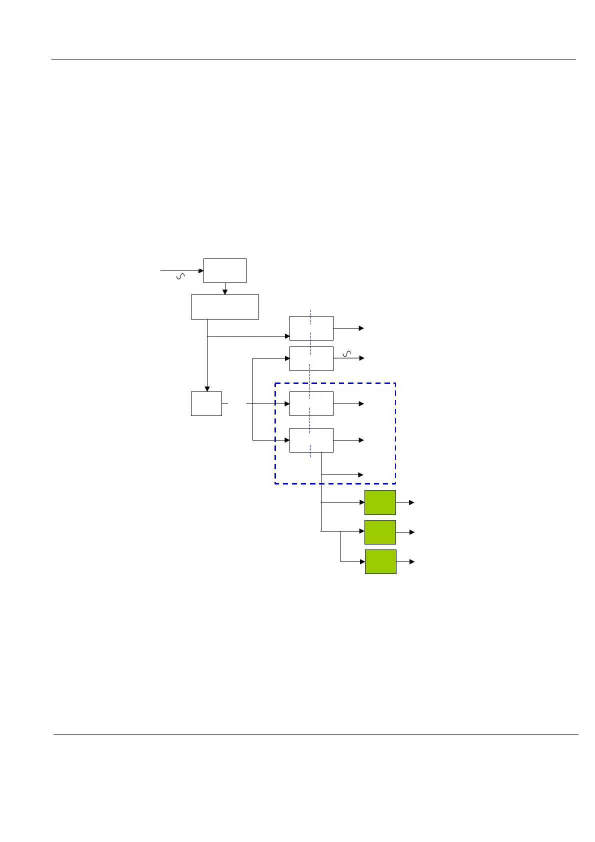
Figure 5-41 Main Power Supply Principle
MLP
Line Filter
Rectifier
Inrush Current
Limiter
PFC
Stand By
+ 5Vstb (12W)
+ 24V
24V
± 48V
+ 48V
+ 15V
+ 12V
+ 6V
TLP
± 0 – 95V
± 0 – 95V
2X20W
IEC60601-1
Isolation
400V
90-250Vac
0-140V
0-140V
130W
Inverter
110V
120VA
113 – 400 V
+ 48V
6V
- 48V
PMX
± 100 V
8W
+/- 48V
 Loading...


