_____ _
User Guide Electrical Line Shaft for ADV200 Page 7 of 72
3 Operating principle
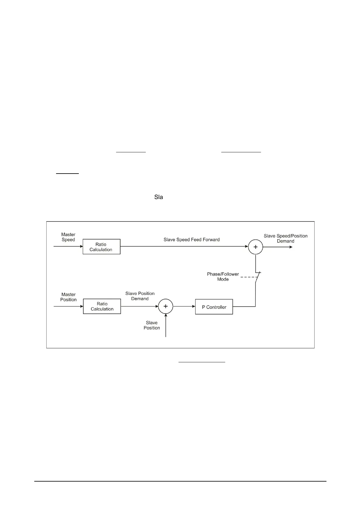
Master drive encoder signals are transmitted to the slave drive in order to derive position and speed
information.
Master position and speed are multiplied by the programmed overall ratio to determine its reference position
and speed for the slave.
The speed reference is the system feed-forward component (base reference), while the reference position,
together with actual position information from the slave motor encoder, is used by a PI control whose output,
added to feed-forward, ensures the phase formula (Els Control Mode = Phase).
A control mode setting parameter lets you exclude the PI control for applications that do not require
maintenance of the phase formula (Els Control Mode = Follower).
The overall ratio is expressed by the following formula:
=
1
1 +
100
where:
•
=
Els Act Mech Ratio
•
: mechanical ratio between Master / Slave (with respect to fast shafts)
• : slip ratio between Slave / Master speeds;
• : slip/correction of
Figure 1. Basic control diagram
3.1 Conditions
The ELS application is not designed for use with two or more motors mechanically linked to
the same load.
When using the ELS application, use the drive in Flux vector CL control mode (mandatory
condition if phase control is required (ELS Control Mode = Phase).
To prevent drift, the coupling ratio must be known and expressed precisely (gear mechanics);
otherwise, drift can be managed only with external correction/compensation systems.
The Master encoder source cannot be the same used by the Flux vector CL control.
 Loading...


