Pre-Installation Information and Recommendations
032-0265-EN Rev 1 3-5
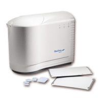
DenOptix QST Laser Scanner
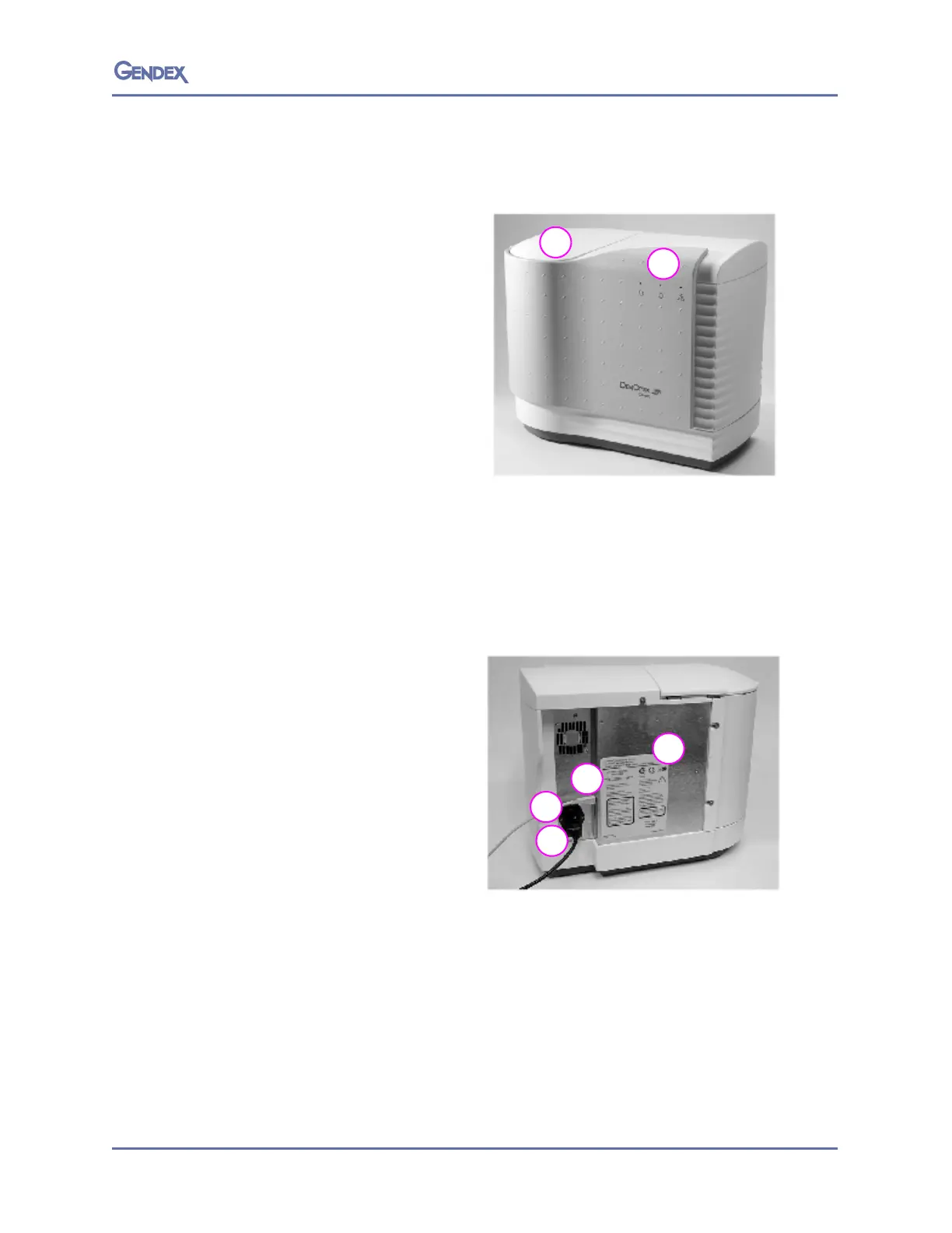
Scanner Front View
1. Carousel well and lid. The lid has a
locking mechanism that engages
during scanning and loss of power
(see page 5-6 or handling
procedure). The carousel, with
imaging plates attached, is
inserted into the carousel well for
scanning. The carousel lid must be
in the closed position prior to
scanning. The scanner will not
operate with the lid open.
2. LED indicator lights with graphic
sym
bols
.
The lights show the current status of the system.
• Gr
een — Ready to scan
• Ye
llow Blinking – Scanning
• Red — Error
Scanner Rear View
1. DenOptix QST scanner power
entry module with switch and
fuses
2. USB 2.0 connector. A USB 2.0
c
ab
le (provided) connects the
DenOptix QST scanner to the
CPU’s USB 2.0 port.
3. Power cord socket. The power
cord
(provid
ed) will be connected
from this point to a grounded
main outlet.
4. Scanner label.
 Loading...