19
Save These Instructions 3-90-775R36_09/15
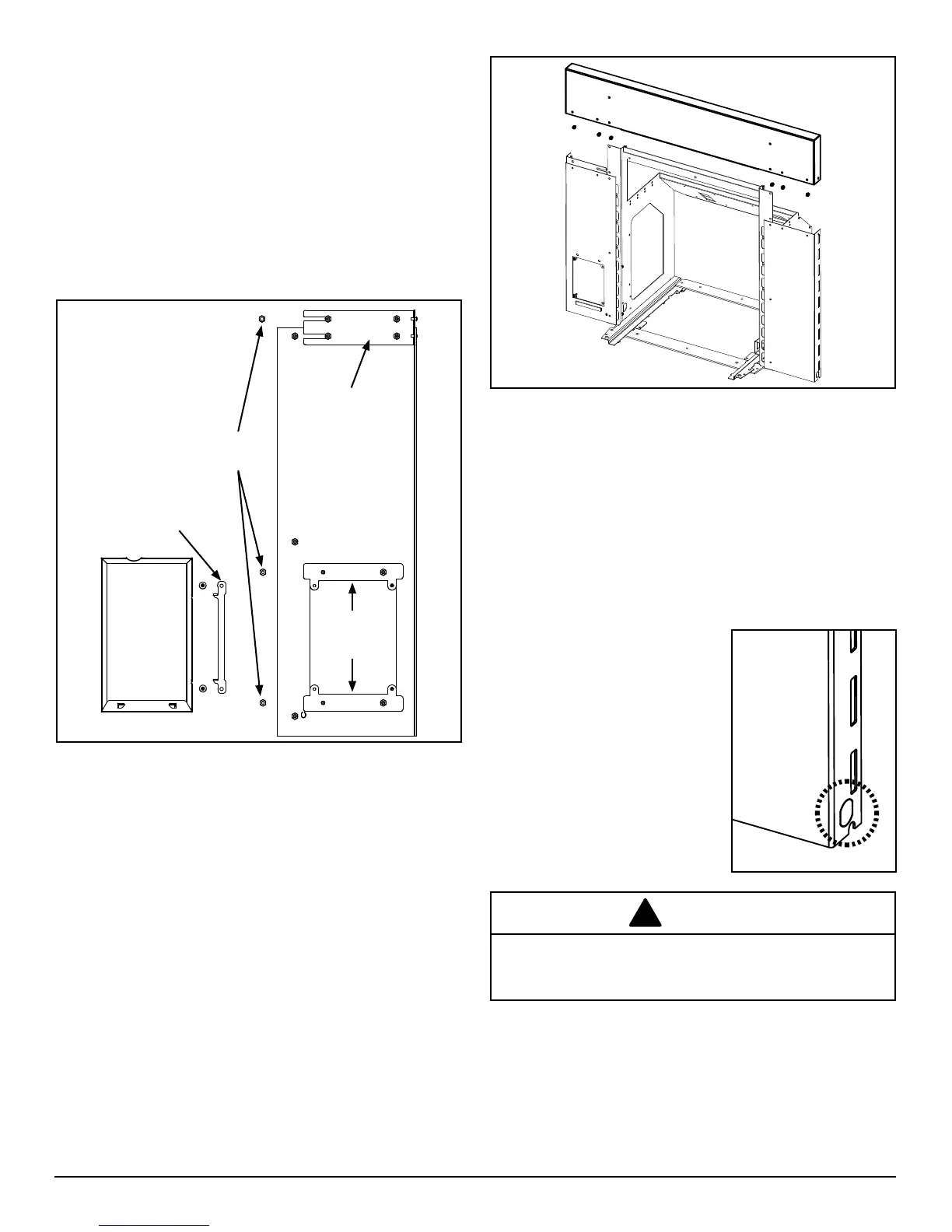
C. Routing the Power Cord
When choosing an electrical supply outlet, be sure the
polarity is correct, and that the supplied voltage is within
the range of 117 to 123 Volts. Surge protection is also
recommended to protect the control board software in the
eventofasurgeorspike.
Oncetheoutletlocationisdecided,you'llneedtoinstalland
route the power cord.
At the bottom of each of the side surround panels is a
knockout for the cord retainer. Remove the appropriate
knockoutandfeedtheloosewireendofthecordintothe
hole. If your cord needs to exit
from the right side, route the cord
up the side and over the top of the
mounting frame and back down
the left side. Use the two hooks
on the top corners of the mounting
frame to secure the cord. Attach a
star washer, the ground wire ring
terminal, a second star washer,
the ring terminal from the ground
wire jumper to the bottom stud of
the left surround panel. Using a
pliers, compress the cord clamp
and push it into the hole.
B. Installing the Surround
The surround consists of three panels, the top and two
sides. Follow these steps for installation:
1. Removetheinsertbodyfromthemountingframe;
2. Startyourlevelingbolts into the oorof theframe and
adjusttoslightlyraisetheheight.(seenextsection)This
will allow some clearance to assemble the surround.
3. Prepare the side panels by removing three nuts each.
The left side panel is the one with the control board
opening.Ifmountingthecontroldoor,thehingebracket
will attach using the control panel mounting screws.
4. Attach the side panels to the mounting frame by guiding
the threaded studs through the holes in the mounting
frame. Slip the power cord ground wire terminal over
the bottom stud on the left side. Install the nuts onto the
studs,ngertightenonly.
5. Installthetoppanel,makingsuretoclosethegapwith
the side panels rst. Tighten the nuts on the splice
bracketssecurely.
6. Set the mounting frame into position in the replace
opening. Be sure the surround panel is raised slightly so
that it is not supporting any of the weight of the mounting
frame.
7. Whenpleasedwiththealignment,tightenallofthenuts
securely.
8. Therearetwomoreholesinthesplicebracketstoalign
the outer sides of the surround panel joints. If desired,
installthesuppliedblackpop-rivetshere.
ROUTE POWER CORD AWAY FROM THE APPLIANCE.
DO NOT RUN THE CORD UNDER OR IN FRONT OF
THE APPLIANCE.
WARNING
Surround
Splice Plate
Control
Mount
Brackets
Control door
and hinge
Three nuts to
secure to the
frame.
 Loading...