21
Save These Instructions 3-90-775R36_09/15
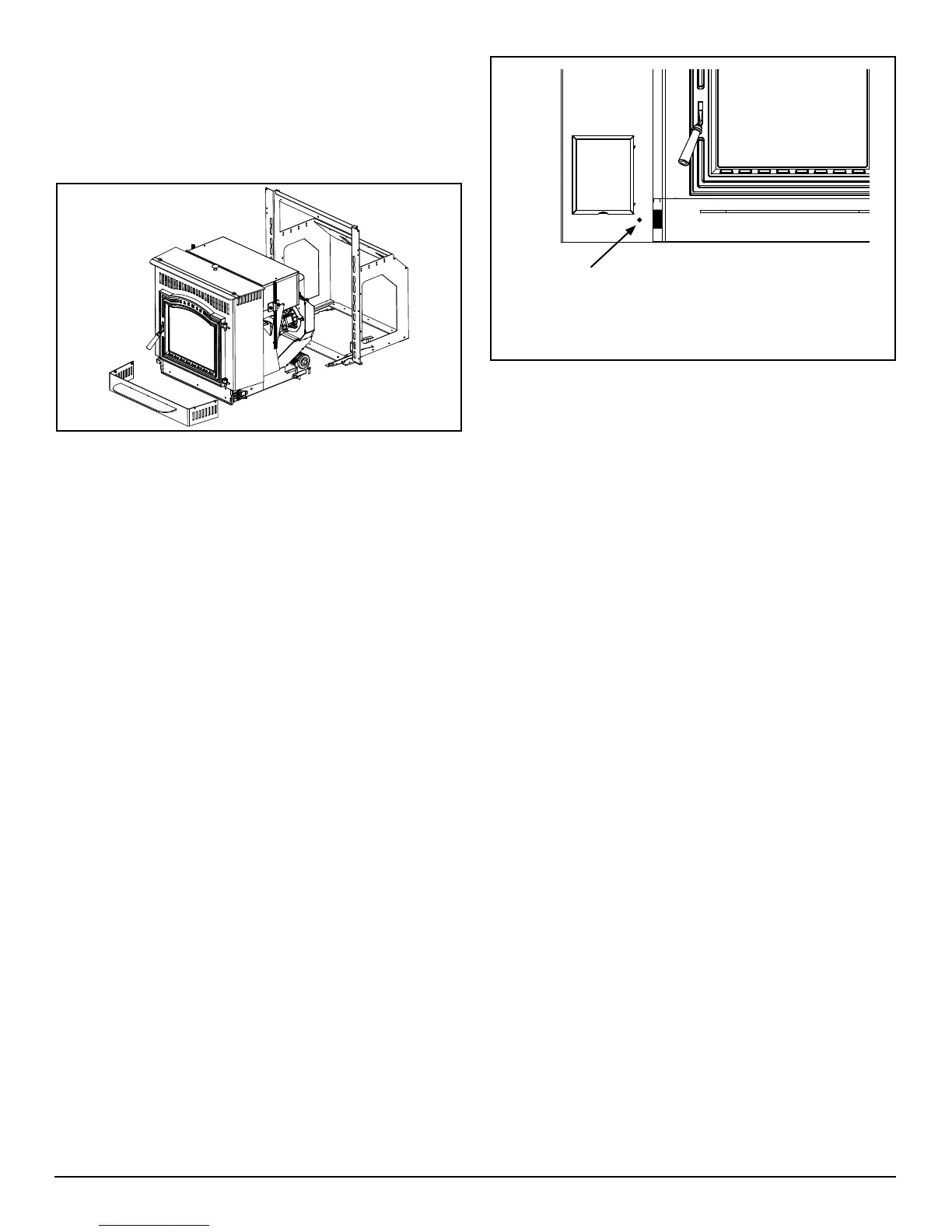
Room sensor placed here gives an accurate measure
of return air. Push the pre-cut hole inward, and feed the
sensorfromthebackside.Allowthebulbofthesensorto
extend approximately 1½" into the room. Use a wire tie on
the push-in tab to secure the sensor wire.
G. Control Board Installation
The control board is packaged in a static resistant bag.
Use care when handling, hold the circuit board only by the
edges.In alarge replaceopening, youmay have plenty
of space for the circuit board to remain attached. For a
smallerreplaceopening,you'lllikelyneedtoremovethe
wiring from the circuit board to route it through the side of
the mounting frame and out through the control opening.
Followthesesteps;
• Disconnect the 11 pin harness plug.
• Disconnect the red twisted ESP wire.
• Feed the harness wires and the ESP wire through the
opening in the mounting frame and out through the
control opening in the surround panel.
• Holding the control board outside the opening in the
surroundpanel,re-attachtheharnessplugandtheESP
wire.
• After determining the location of the Room Sensor (See
nextSection),Attachittothetwomalespadeterminals
near the top of the circuit board.
NOTE:Theseconnectionsarenotpolarityspecic.
• From the power cord, attach the green ground wire
tothegroundingpostlocatedonthefeederairintake
snout.
• Theblackwirefromthepowercordgetsattachedtothe
short brown wire from the control harness
• The white wire from the power cord will attach to the
short white wire on the control harness.
• Install the control panel into the surround; Right side
rst,thentiltintheleftside.
• Secureusingthe four blackmachinescrewsincluded
with the surround.
H. Room Sensor Installation
Although not required, it is recommended that the room
sensor be connected in every installation. Using a minimum
size 18 gauge wire, you may splice in an additional length, to
extendtheroomsensor.Thefollowingaretypicallocations
fortheroomsensor;
• Onaninteriorwallnexttoorinplaceofatypicalwall
thermostat.
• Onthelegofacoffeetableorendtableinyourfavorite
sitting location.
• Stickingoutthroughthepunchedholeatthelowerright
corner of the control panel.
Note: When installing the room sensor externally, limit
thedistancefromthestoveto25feetorless.
Oncethelocationhasbeendecided,runthewiringtothe
control panel. You'll need to remove the two terminals from
the end of the sensor cable and replace them with the two
smaller terminals from the hardware bag. Plug the terminals
into the circuit board. These connections are not polarity
specic.
Note: If the room sensor is located too close to the
appliance,orinadirectpathofthedistributionair,You
may need to elevate the temperature setting to maintain
acomfortabletemperaturelevelthroughouttheheated
space.
See Section E. Draft Test Procedure under Operating
Instructions.
F. Installing the Body into the Mounting Frame
Attach the female terminal of the ground jumper wire to the
groundlugontheairintake.Therollersonthesidesofthe
insertbodywillrideontherailsofthemountingframe.Once
the body is all the way in, hook and close the top spring
latches on each side to secure.
 Loading...