20
Save These Instructions3-90-775R36_09/15
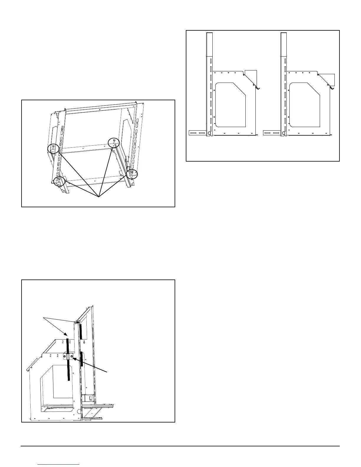
E. Attaching the Venting
Theuecollarontherearofthemountingframeisdesigned
to pivot. Loosen the four mounting bolts and adjust the angle
of the collar as needed. Shown above is the vertical position
and the horizontal position.
D. Securing the Mounting Frame
Themountingframeistheanchorfortheappliance.If
the frame is not secured properly, shifting will occur
when sliding the insert in or out.
ThestoveissuppliedwithaLegLevelerKitthatcontains(4)
5/16-18X1".Theseboltsshouldbethreadeddownthrough
the holes to raise the frame corners as needed, to level.
Themountingframeistheanchorfortheappliance.If
the frame is not secured properly, shifting will occur
when sliding the insert in or out.
NOTE:Wheninstalledinarearventconguration,themaximum
BTU may be reduced due to elevated ESP temperatures
associatedwiththehorizontalexhauststream.
Leveler Bolts
With the surround attached and the power cord installed,
install the coupler nut weldments to the frame in the hole
locationthatsuitsyourneedswiththe(4)1/4-20x5/8ange
screws and nuts and 1/2” jack bolts. Install the (4) 5/16”-
18 leveling bolts into the threaded holes in the bottom pan
of the mounting frame, install the mounting frame into the
opening and adjust these bolts to insure the frame is level.
(NOTE:Useofall4levelingboltsmaynotbenecessary.)
Tightenthe½”jackboltsagainstthelintel.
JackBolts
Coupler weldment and
1/4-20x5/8"Flangebolts
Install the coupler nut weldments to the frame with the
(4)1/4-20x5/8angescrewsandnuts.Tightenthe½”
jackboltsagainstthelintel.
 Loading...