Checking parts:
– Examine the piston for score marks or
wear.
– Check the valve seat (111/19) for wear.
– Renew the O-rings.
Assembling the engine monitoring
block:
– Proceed in the reverse order of work
for removal.
Note:
To install the piston, use auxiliary bushing
- 34 -.
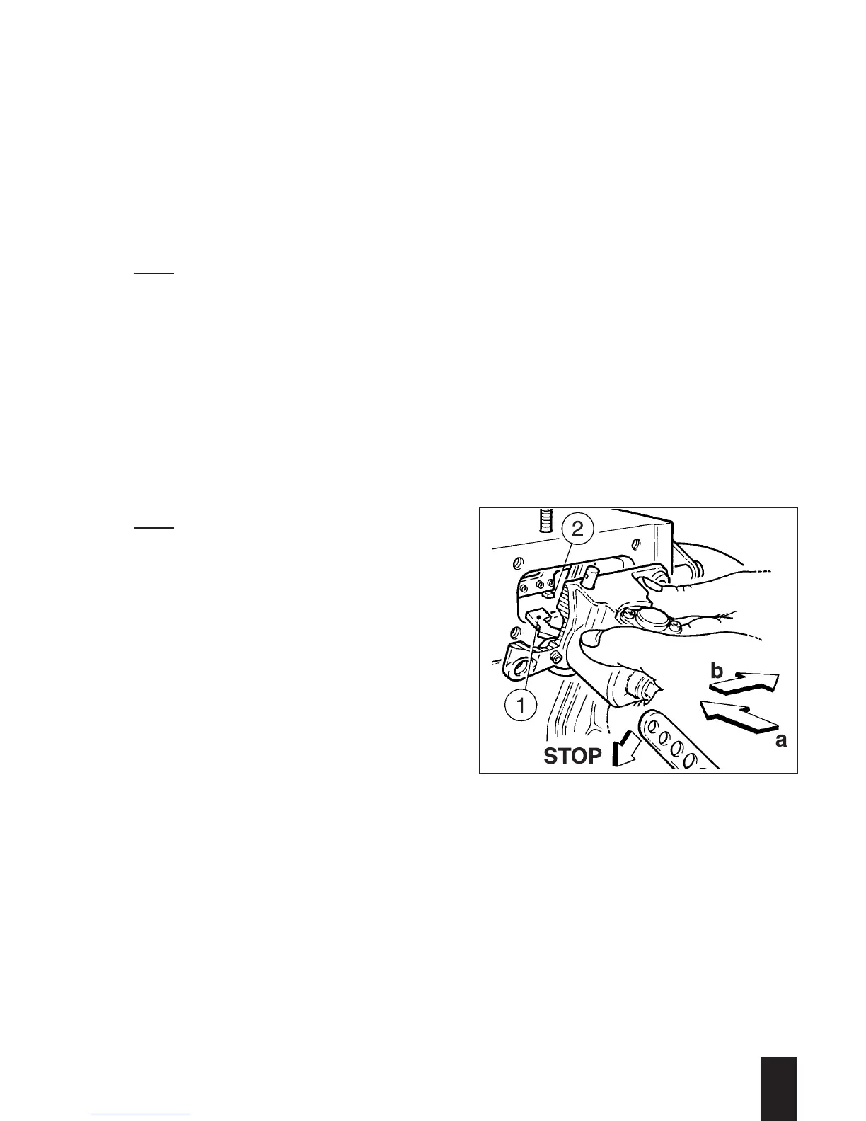
Assembly:
– Move the speed control lever to the
„Stop“ position.
– To attach, follow the instructions for de-
taching the device in the reverse order.
– Make sure that the gasket is correctly
seated and note the scribed mark which
indicates the correct position; install the
machine screws with sealant D.
Note:
When attaching, make sure that lever
(112/1) engages to the left of plate
(112/2). To do this on engines with the lo-
wer idle speed governed to ≥ 1700 rpm
the shaft (111/12) must be turned coun-
ter-clockwise when assembling. Check
when the monitoring block is installed by
turning shaft (111/12) counter-clockwise;
it must then move back by itself to its initi-
al position.
Adjusting the engine monitoring block:
– The maximum fuel injection volume is
adjusted by turning the piston (111/18).
For adjusting the fuel injection volume
and the correct procedure see section
M 14.00. If the same monitoring block is
detached and re-attached, the fuel in-
jection volume does not need to be ad-
justed, provided that the setting of
piston (111/18) was not altered.
If the monitoring block is renewed or after
it has been repaired, the fuel injection vo-
lume (power setting) must always be
adjusted.
3
L / M . . 09.96
112
 Loading...