30
Part Names and Functions; Screens
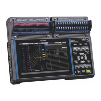
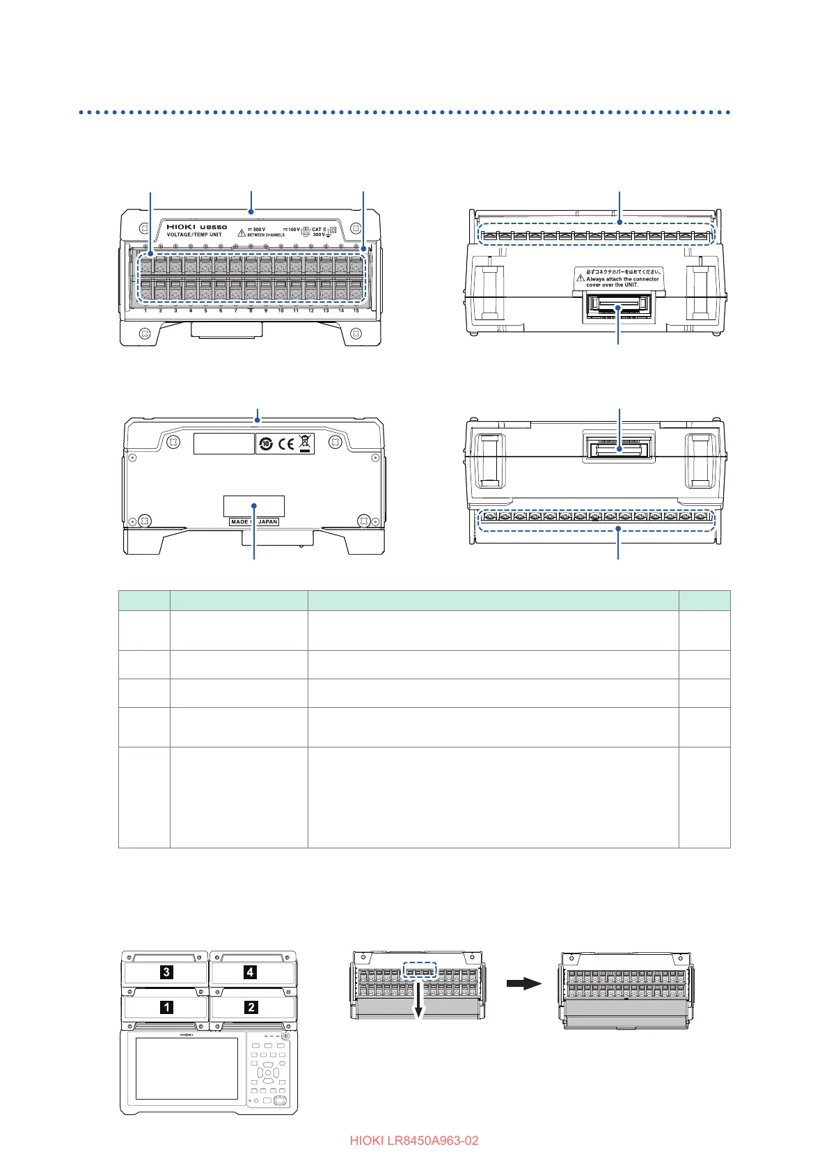
Plug-in modules
Figures show the U8550 Voltage/Temp Unit.
55
22
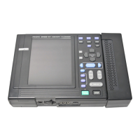
Front Top
Rear Bottom
11
44
11
44
11
33
22
No. Name Functionality See
11
Input terminals Provides input terminals for each channel. The numerics
represent the channel numbers.
p. 49
22
Connector cover Protects the plug-in unit’s input terminals.
p. 38
33
Terminal block cover Close the cover during measurement.
p. 30
44
Connector Used for module expansion.
Attach the connector cover to any unused connectors.
p. 38
55
Serial number The serial number consists of nine digits. The rst two digits
indicate the year of manufacture, while the second two digits
indicate the month of manufacture. Do not remove this sticker as
the number is important.
Communicate this number when you contact your authorized
Hioki distributor or reseller.
–
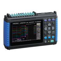
The LR8534 Wireless Strain Unit has the DIP switch, used to select the wiring method.
See “Connecting a strain gage or converter” (p. 58).
Terminal block covers open toward you.
If four plug-in modules have
been installed
Terminal block cover

 Loading...