31
Part Names and Functions; Screens
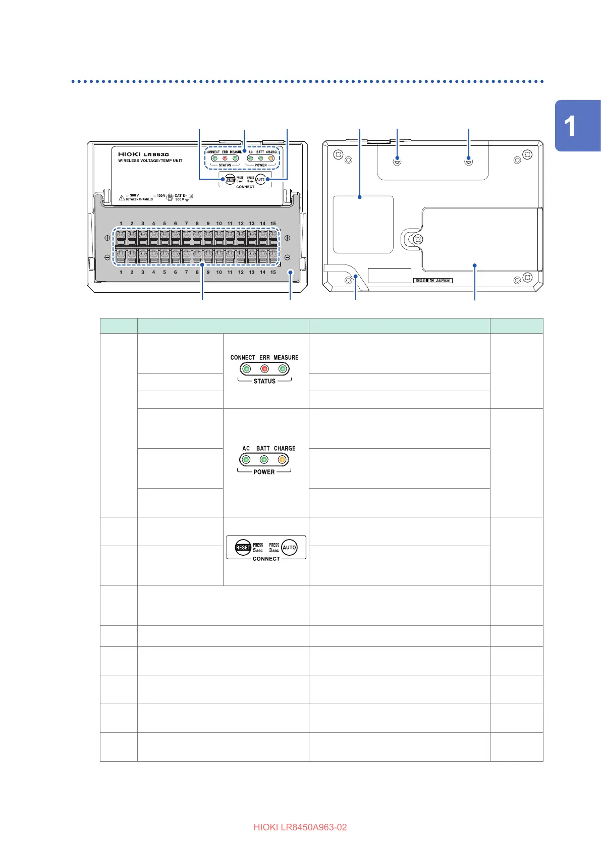
Wireless modules
Figures show the LR8530 Wireless Voltage/Temp Unit.
99 88
777766
11
44
55
22
33
Front Rear
No. Name Functionality See
11
CONNECT LED
Remains on during communications.
Blinks during registration or low-signal
state.
p. 105
ERR LED Lights up when an error occurs.
MEASURE LED Remains on during measurement.
AC LED
Lights up when the instrument is being
powered by the AC Adapter or by an
external power supply.
p. 67
BATT LED Lights up when the instrument is operating
on battery power.
Blinks when the battery is low.
CHARGE LED Lights up when the Battery Pack is being
charged.
22
RESET key
Resets the wireless module’s
communications settings.
p. 73
33
AUTO key Automatically congures communications
settings between the LR8450-01 and the
wireless modules.
44
Input terminals Provides input terminals for each channel.
The numerics represent the channel
numbers.
p. 49
55
Terminal block cover Close the cover during measurement.
p. 32
66
Warning Contains important information about the
wireless module.
–
77
Installation screw holes Accommodates screws for use in mounting
the module on a board or wall.
p. 74
88
Battery compartment Provides internal space for the Z1007
Battery Pack.
p. 40
99
Cable guide Hitch the Z1008 AC Adapter’s cord to
prevent the cord unplugged.
p. 47
The LR8531 Wireless Universal Unit has the power terminal for the Z2000 Humidity Sensor.
See “Connecting the Humidity Sensor” (p. 55).
The LR8534 Wireless Strain Unit has the DIP switch, used to select the wiring method.
See “Connecting a strain gage or converter” (p. 58).
Overview

 Loading...