64
Connecting the Cables
1
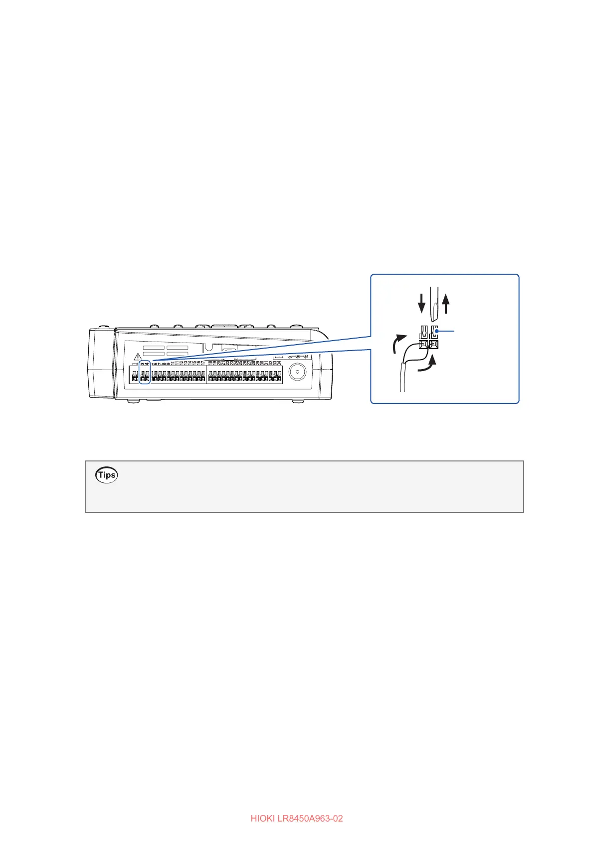
Position the instrument so that the external control terminals on its side are facing you.
2
Press down on the button for the voltage output terminal 1 or voltage output terminal 2 with
the at-head screwdriver.
3
Insert the positive (+) cable into the terminal hole while depressing the button.
4
Remove the at-head screwdriver from the button.
The cable will be locked in place. Pull gently on the cable and verify that it does not come out.
5
Press down on the GND terminal button with the at-head screwdriver.
There are 10 GND terminals. The wire can be connected to any of the GND terminals.
6
Insert the negative (−) cable into the terminal hole while depressing the button.
7
Remove the at-head screwdriver from the button.
The cable will be locked in place. Pull gently on the cable and verify that it does not come out.
22 44
33
Example connecting to voltage output 2
and GND
Terminal
button
How to check the pin assignments of the external control terminals
Press the QUICK SET key, and choose [External connection guide]. Names of the external
control terminals will be displayed.

 Loading...