MSLXU
SAFETY PRECAUTIONS
NOTICE: Comply with all cautions
located on or inside the cabinet and
tllhe
and safety-related notes
on the chassis or picture
WARNING: Since the chassis of this receiver is connected to
one side of the AC power supply during operation, whenever the
receiver is plugged in, service should not be attempted by any-
one unfamiliar with the precautions necessary when working on
this type of receiver.
The following precautions should be observed:
1. Do not install, remove, or handle the picture tube in any man-
ner unless shatterproof goggles are worn. People not so
equipped should be kept away from the picture tube while han-
dling.
2. When service is required, an isolation transformer should be
inserted between power line and the receiver before any serv-
ice is performed on a “HOT” chassis receiver.
3. When replacing a chassis in the receiver, all the protective
devices must be put back in place, such as barriers, nonmetal-
lic knobs, adjustment and compartment cover-shields, isolation
resistors, capacitors, etc.
4. When service is required, observe the original lead dress in the
high voltage circuitry area.
5. Always use the manufacturer’s replacement components.
Critical components as indicated on the circuit diagram should
not be replaced by another manufacturer’s, Furthermore, where
a short circuit has occurred, replace those components that
indicate evidence of overheating.
6. Before returning a serviced receiver to the customer, the serv-
ice technician must thoroughly test the unit to be certain that it
is completely safe to operate without danger of electrical shock,
and be sure that no protective device built into the receiver by
the manufacturer has become defective, or inadvertently
defeated during servicing.
Therefore, the following checks should be performed for the con-
tinued protection of the customer and service technician.
Leakage Current Cold Check
With the AC plug removed from the 120V AC 60Hz source, place
a jumper across the two plug prongs. Using an insulation tester
(DCSOOV), connect one lead to the jumpered AC plug and touch
the other lead to each exposed metal part (antennas, screwheads,
metal overlays, control shafts, etc.), particularly any exposed
metal part having a return path to the chassis should have a min-
imum resistor reading of 0.24MG and a maximum resistor read-
ing of 12MG. Any resistance value below or above this range indi-
cates an abnormality which requires corrective action. An exposed
metal part having a return path to the chassis will indicate an open
circuit.
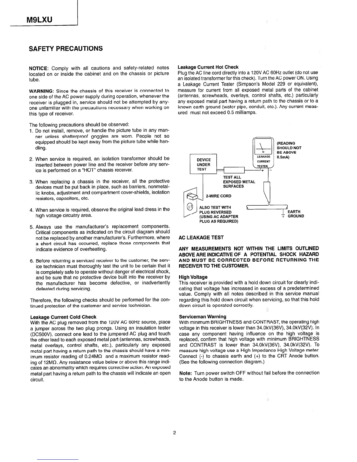
Leakage Current Hot Check
Plug the AC line cord directly into a 12OV AC 60Hz outlet (do not use
an isolated transformer for this check). Turn the AC power ON. Using
a Leakage Current Tester (Simpson’s Model 229 or equivalent),
measure for current from all exposed metal parts of the cabinet
(antennas, screwheads, overlays, control shafts, etc.) particularly
any exposed metal part having a return path to the chassis or to a
known earth ground (water pipe, conduit, etc.). Any current meas-
ured must not exceed 0.5 milliamps.
(READING
SHOULD NOT
BE ABOVE
OSmA)
I
TEST ALL
EXPOSED METAL
AED
PLUG AS REQUIRED)
AC LEAKAGE TEST
ANY MEASUREMENTS NOT WITHIN THE LIMITS OUTLINED
ABOVE ARE INDICATIVE OF A POTENTIAL SHOCK HAZARD
AND MUST BE CORRECTED BEFORE RETURNING THE
RECEIVER TO THE CUSTOMER.
High Voltage
This receiver is provided with a hold down circuit for clearly indi-
cating that voltage has increased in excess of a predetermined
value. Comply with all notes described in this service manual
regarding this hold down circuit when servicing, so that this hold
down circuit is operated correctly.
Serviceman Warning
With minimum BRIGHTNESS and CONTRAST, the operating high
voltage in this receiver is lower than 34.0kV(36V), 34.0kV(32V). In
case any component having influence on the high voltage is
replaced, confirm that high voltage with minimum BRIGHTNESS
and CONTRAST is lower than 34.0kV(36V), 34.0kV(32V). To
measure high voltage use a High Impedance High Voltage meter.
Connect (-) to chassis earth and (+) to the CRT Anode button.
(See the following connection diagram.)
Note: Turn power switch OFF without fail before the connection
to the Anode button is made.
2
 Loading...