M9LXU
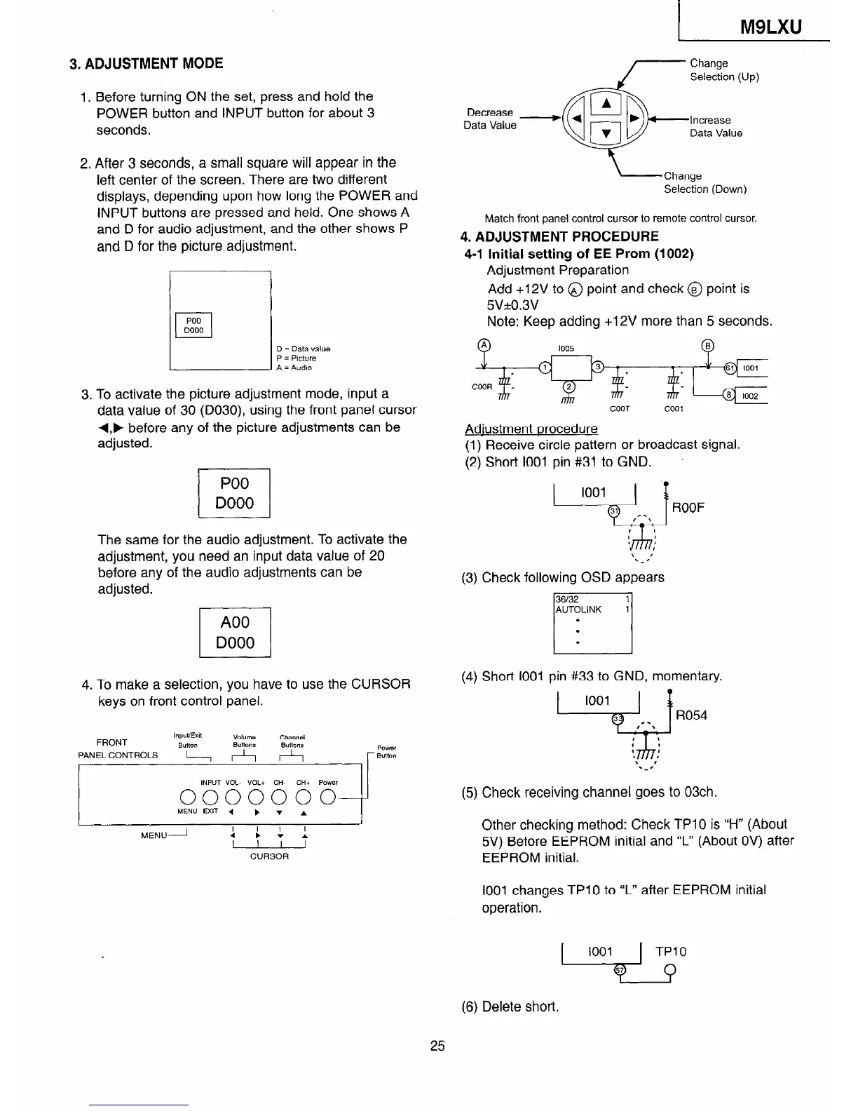
3. ADJUSTMENT MODE
1.
2.
3.
Before turning ON the set, press and hold the
POWER button and INPUT button for about 3
seconds.
After 3 seconds, a small square will appear in the
left center of the screen. There are two different
displays, depending upon how long the POWER
and
INPUT buttons are pressed and held. One shows A
and D for audio adjustment, and the other shows P
and D for the picture adjustment.
El
PO0
El
DO00
D = Data value
P = Picture
A = Audio
To activate the picture adjustment mode, input a
data value of 30 (D030), using the front panel cursor
+,, before any of the picture adjustments can be
adjusted.
PO0
/
DO00
The same for the audio adjustment. To activate the
adjustment, you need an input data vatue of 20
before any of the audio adjustments can be
adjusted.
4. To make a selection, you have to use the CURSOR
keys on front control panel.
Input/Exit
FRONT
Volume
Channel
Bum
Buttons
Butions
PANEL CONTROLS
L---lG-lA
PW/er
r Button
, , ,
I
INPUT V/oL- VOL+ CH-
CH+ Power
I I
0000000
MENU EXIT
4
b v A
I
MENU-- Ir
I 1 I
:
CURSOR
Decrease
Data Value
Increase
Data Value
-Change
Selection (Down)
Match front panel control cursor to remote control cursor,
4. ADJUSTMENT PROCEDURE
4-l Initial setting of EE Prom (1002)
Adjustment Preparation
Add +12V to @ point and check @ point is
5v+o.3v
Note: Keep adding +12V more than 5 seconds.
+
+
@J 1001
COOT coo1
Adiustment procedure
(I) Receive circle pattern or broadcast signal.
(2) Short 1001 pin #31 to GND.
ROOF
(3) Check following OSD appears
AUTOLINK 1
(4) Short 1001 pin #33 to GND, momentary.
(5) Check receiving channel goes to 03ch.
Other checking method: Check TPlO is Y-l” (About
5V) Before EEPROM initial and “L” (About OV) after
EEPROM initial.
1001 changes TPlO to “L” after EEPROM initial
operation.
(6) Delete short.
25
 Loading...