MSLXU
CUSTOM MENU
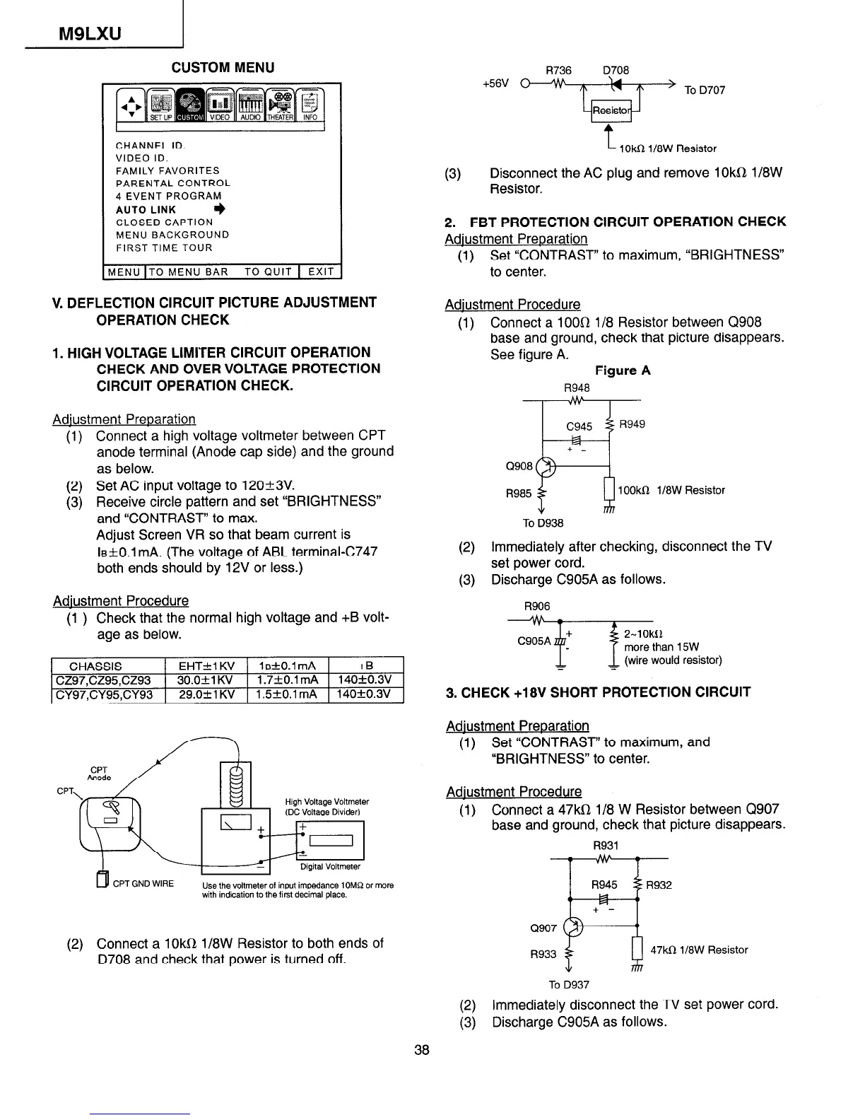
CHANNEL ID.
VIDEO ID.
FAMILY FAVORITES
PARENTAL CONTROL
4 EVENT PROGRAM
AUTO LINK
+
CLOSED CAPTION
MENU BACKGROUND
FIRST TIME TOUR
AENU IT0 MENU BAR TO QUIT 1 EXIT
V. DEFLECTION CIRCUIT PICTURE ADJUSTMENT
OPERATION CHECK
1. HIGH VOLTAGE LIMITER CIRCUIT OPERATION
CHECK AND OVER VOLTAGE PROTECTION
CIRCUIT OPERATION CHECK.
Adiustment Preparation
(1) Connect a high voltage voltmeter between CPT
anode terminal (Anode cap side) and the ground
as below.
(2) Set AC input voltage to 12O-t3V.
(3) Receive circle pattern and set “BRIGHTNESS”
and “CONTRAST” to max.
Adjust Screen VR so that beam current is
le+O.l mA. (The voltage of ABL terminal-C747
both ends should by 12V or less.)
Adiustment Procedure
(1 ) Check that the normal high voltage and +B volt-
age as below.
CHASSIS EHT+l KV 1 sfO.1 mA +B
cz97,cz95,cz93 30.0+1 KV 1.7kO.l mA 140+0.3v
29.0&l KV 1.5fO.l mA 140f0.3V
I
CY97.CY95.CY93
I
I I
CP
CPT GND WIRE
i input impedance 1OMQ or more
with indication to the first decimal place.
(2) Connect a 1Okfi 1/8W Resistor to both ends of
D708 and check that power is turned off.
R736 D708
+56V O--‘#
‘u
’ To D707
(3)
Resist0
t
1 Okfi 118W Resistor
Disconnect the AC plug and remove 1 Okfl1/8W
Resistor.
2. FBT PROTECTION CIRCUIT OPERATION CHECK
Adiustment Preparation
(1) Set “CONTRAST” to maximum, “BRIGHTNESS”
to center.
Adiustment Procedure
(1) Connect a 1 OOfl l/8 Resistor between Q908
base and ground, check that picture disappears.
See figure A.
Figure A
R948
c945
I3949
+ -
R
Q908
R985
lOOk 1/8W Resistor
To D938
(2)
Immediately after checking, disconnect the TV
set power cord.
(3) Discharge C905A as follows.
R906
ZW!;; vstor,
=
3. CHECK +18V SHORT PROTECTION CIRCUIT
Adiustment Preparation
(1) Set “CONTRAST” to maximum, and
“BRIGHTNESS” to center.
Adiustment Procedure
(1) Connect a 47kfi l/8 W Resistor between Q907
base and ground, check that picture disappears.
R931
R945 R932
+ -
H
Q907
R933
47kfi 1/8W Resistor
To D937
(2) Immediately disconnect the TV set power cord.
(3)
Discharge C905A as follows.
 Loading...