E1 Series Servo Drive EtherCAT(CoE) Communications Command Manual EtherCAT Communication
2-16 HIWIN MIKROSYSTEM Corp.
Table 2.9.1.1
Node address switch setting Descritpion
The node address is set by the controller.
The node address switch setting is used as the node address.
Note: Do not change node address setting after control power-on.
2.9.2 EtherCAT indicators
There are four EtherCAT indicators (LED),RUN, ERR, L/A IN and L/A OUT, on E1-series CoE drive. RUN
indicator shows the status of ESM. ERR indicator shows the error status of EtherCAT communication. As
for L/A IN and L/A OUT indicator, they shows the physical link states and operation statuses of EtherCAT
IN and OUT port. The states of each indicator are described in Table 2.9.2.1.
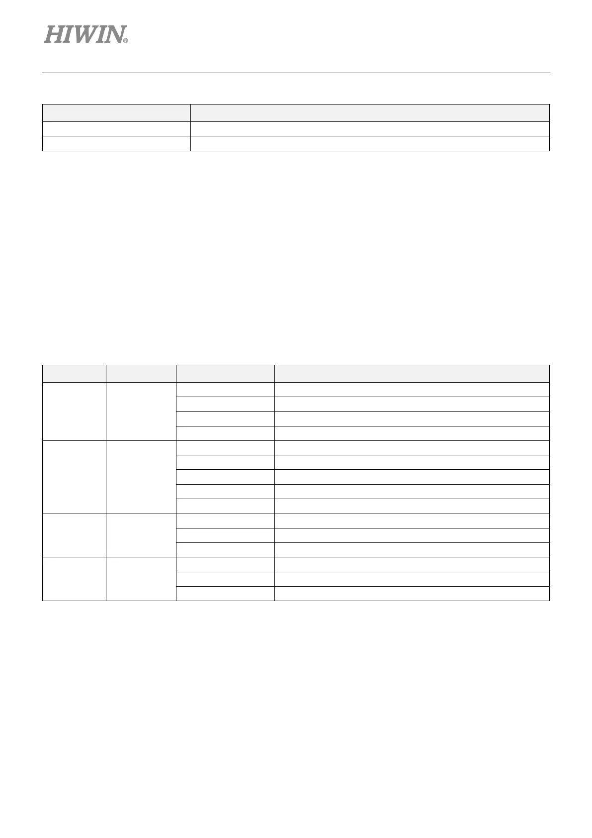
Table 2.9.2.1
Name LED color State Description
RUN Green
ERR Red
Communication setting error
Application watchdog timer (WDT) timeout
L/A IN Green
Link not established in physical layer
Flickering In operation after establishing link
Link established in physical layer
L/A OUT Green
Link not established in physical layer
Flickering In operation after establishing link
Link established in physical layer

 Loading...


