E1 Series Servo Drive EtherCAT(CoE) Communications Command Manual Object Dictionary
3-12 HIWIN MIKROSYSTEM Corp.
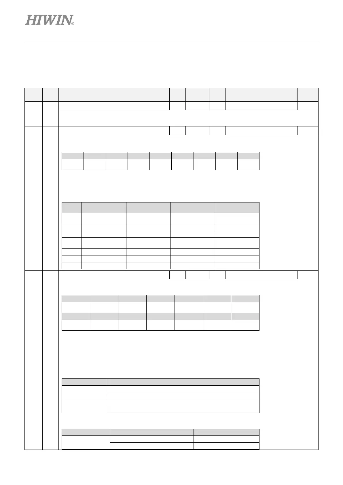
3.2 Standardized device profile area
Table 3.2.1
Index
Sub-
Index
Name
Data
type
Access PDO Valid value Unit
603Fh 00h
Error code U16 ro Y 0x0 ~ 0xFFFF -
Display the last error that occurs.
The value of the error code is FF**h, where ** is the error code from E1-series drive.
Take FF10h as an example. 10h = 16d → Error 16 occurs.
6040h 00h
Controlword U16 rw Y 0x0 ~ 0xFFFF -
The object controls the drive’s PDS state transition and the specific commands in operation mode. The details of the bits are
described as below.
15 ... 10 9 8 7 6 ... 4 3 2 1 0
N/A
halt
Bit 8 (halt): If it is set to 1, the motor decelerates and stops according to object 605Dh (halt option code). Setting the bit to 0
will resume the halt operation. It is only applicable in pp, pv, tq and hm mode.
Bit 7, 3~0: PDS commands. The codes of the commands are described in Section 3.2.1 PDS (Power Drive System).
Bit 9, 6~4 (operation mode specific): The availability of each bit in each mode is listed as below.
9 6 5 4
pp change on set-point absolute / relative
new set-point
hm - - -
csp - - - -
6041h 00h
Statusword U16 ro Y 0 ~ FFFFh -
The object provides the status of PDS FSA and the specific information in operation mode. The details of the bits are described
as below.
15 14 13 12 11 10 9 8 7
Reserved
Remote Reserved Warning
Quick stop
Fault
Switched on
Bit 6, 5, 3~0: PDS states. The codes of the states are described in Section 3.2.1 PDS (Power Drive System).
Bit 4 (voltage enabled): If the main power is applied to PDS, the bit is set to 1.
Bit 5 (quick stop): If PDS is reacting on a quick stop request, the bit is set to 0.
Bit 7 (warning): If the bit is 1, it indicates a warning occurs. PDS does not change and the operation of the motor continues
during warning (no error occurs).
Bit 9 (remote): Controlword is processed if the bit is set to 1. It will be set to 1 after ESM state becomes PreOp (SDO available).
Bit 10 (target reached):
0
Halt (Bit 8 in controlword) = 0: target not reached
Halt = 1: axis decelerates
1
Halt = 1: axis stops (velocity = 0)
Bit 11 (internal limit active): The bit is set to 1 if one of the following conditions occurs.
Op mode Condition Servo on / off
Position
control
pp, csp
Software limit on / off

 Loading...


