Installation SmartRadar FlexLine
Part No.: 4417.760_Rev06 Installation Guide
31
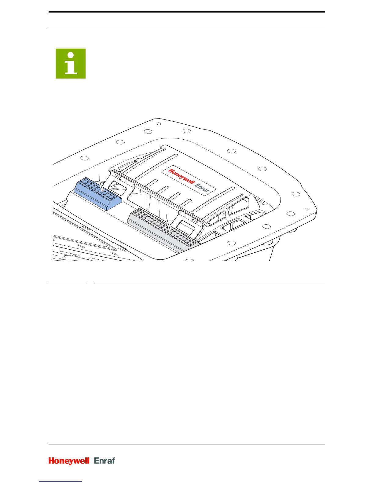
4.11.2.3 Terminals
FIG. 4-7 Terminal layout without SmartConn
The terminal compartment is divided into two zones:
Blue terminals (A), for intrinsically safe connections, such as
HART, VITO and SmartView.
Grey terminals (B), for non-intrinsically safe connections.
The indices of the terminals are variable. For each option there
are indices on the terminal row. They are specified in a label
attached in front of the terminal row, as is schematically indicated
in figure 4.8.
The terminals for the power supply are standard.
Some terminal contacts can be double labelled. In this case the
white text on black label is the first option for connection. The
black text on white label is the second option for connection.
NOTE:
The SmartConn box is also available with 6 cable
entries.
 Loading...