Periphery components for ESSER FACP
TI 798960.GB0 / 04.20 47
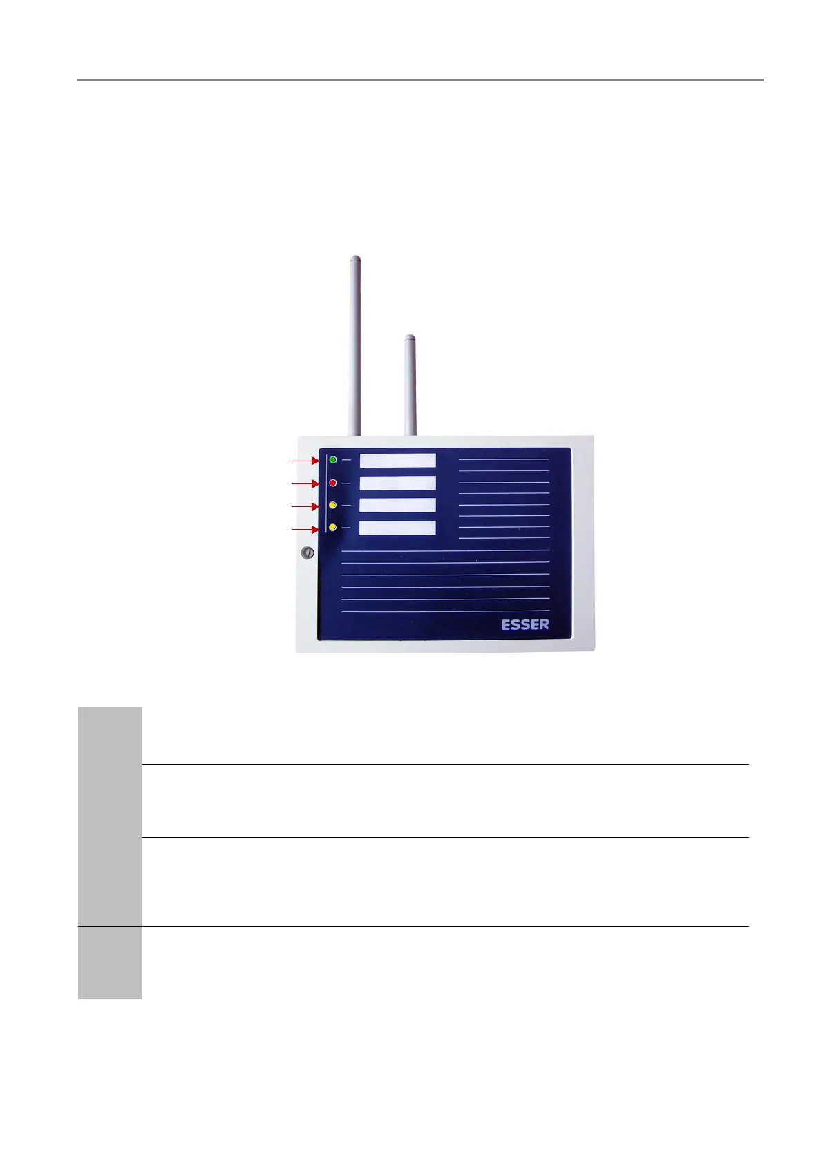
7.1 IQ8Wireless transponder
The mounting position of the IQ8Wireless transponder (Part No. 805595.10) should be chosen to ensure a good
radio connection (field strength) between the IQ8Wireless transponder and the associated IQ8Wireless detector
bases.
The four LED, each with their own description field, on the front of the housing provide information about the
status of the wireless transponder.
Fig. 34: IQ8Wireless transponder
LED 1
Operation (green)
lights up when in normal operation
LED 2
Common fire (red)
lights up if the fire alarm of an assigned RF device is detected. The relay >Common fire< is
activated.
LED 3
Common fault (yellow), display not stored
lights up if a fault alarm of the IQ8Wireless transponder or assigned Wireless device is detected.
The activation of the relay >common fault< is interrupted and the relay contact changes the
switching status.
LED 4
Initialisation (yellow)
Lights up during the activation / recognition process of the IQ8Wireless transponder when the
Wireless device is detected.
 Loading...