LDM Series Instruction Manual — P/N 15885:H3 8/12/2019 43
AIM-200 Point Annunciation System 5000 (UL 8th)
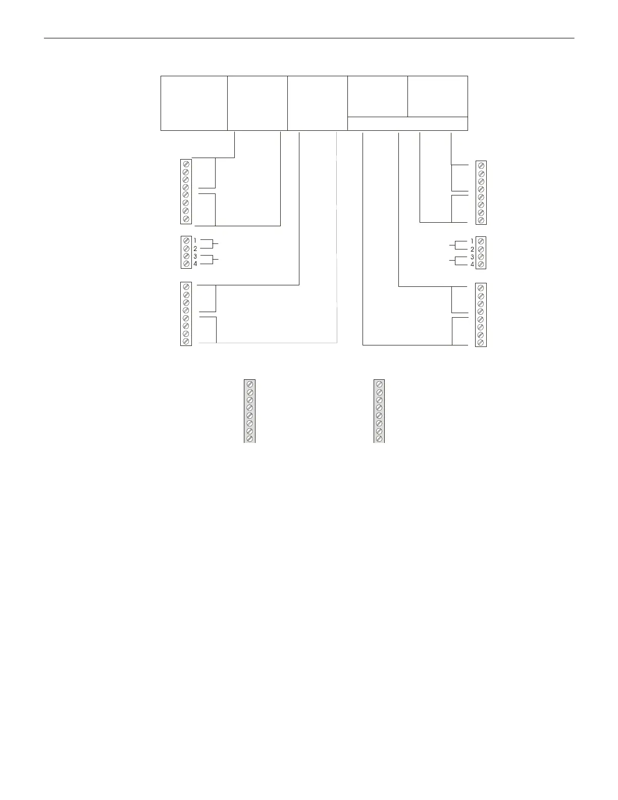
Figure B.11 illustrates the configuration of the LDM-R32 Relay Expander to activate alarms and troubles for up to 56 zones with the last
eight relays dedicated to the CPU functions listed below.
1
2
3
4
5
6
7
8
TB 3
TB 4
TB 5
TB 2
TB6
TB 1
1
2
3
4
5
6
7
8
1
2
3
4
5
6
7
8
TB2
Address #1
LDM-32
1st LDM-E32
2nd LDM-E32
3rd LDM-E32
System Status Indicators *
1 - 4
17 - 20
33 - 36
49 - 52
5 - 8
21 - 24
37 - 40
53 - 56
9 - 12
25 - 28
41 - 44
13 - 16
29 - 32
45 - 48
N.O. Contacts
N.O. Contacts
N.O. Contacts
N.O.
Contacts
Trouble
Alarm
Alarm
Trouble
Trouble
Alarm
Alarm
Trouble
Common for TB1
Common for TB2
Common
for TB3
* System Functions
System Alarm
not used
not used
not used
System Trouble
Signals Silenced
not used
Supervisory
NAC Circuit #1 ON
NAC Circuit #2 ON
Municipal Tie ON
Alarm Relay ON
NAC Circuit #1 Trouble
NAC Circuit #2 Trouble
Municipal Tie Trouble
Alarm Relay Trouble
Common
for TB4
* It is assumed that the '8-Point Shift' will be selected only on systems containing less than 56 circuits.
Figure B.11 Alarm and Trouble Relays with 8-Point Shift

 Loading...