LDM Series Instruction Manual — P/N 15885:H3 8/12/2019 61
Configuration for the LDM-32 and AFP-200 AFP-200 (UL 8th)
Alarm and Trouble Mode With 8-Point Shift
It is assumed that systems with 8-Point Shift selected will be 56 zones or less.
Table E.1 LDM Series Switch Control Functions
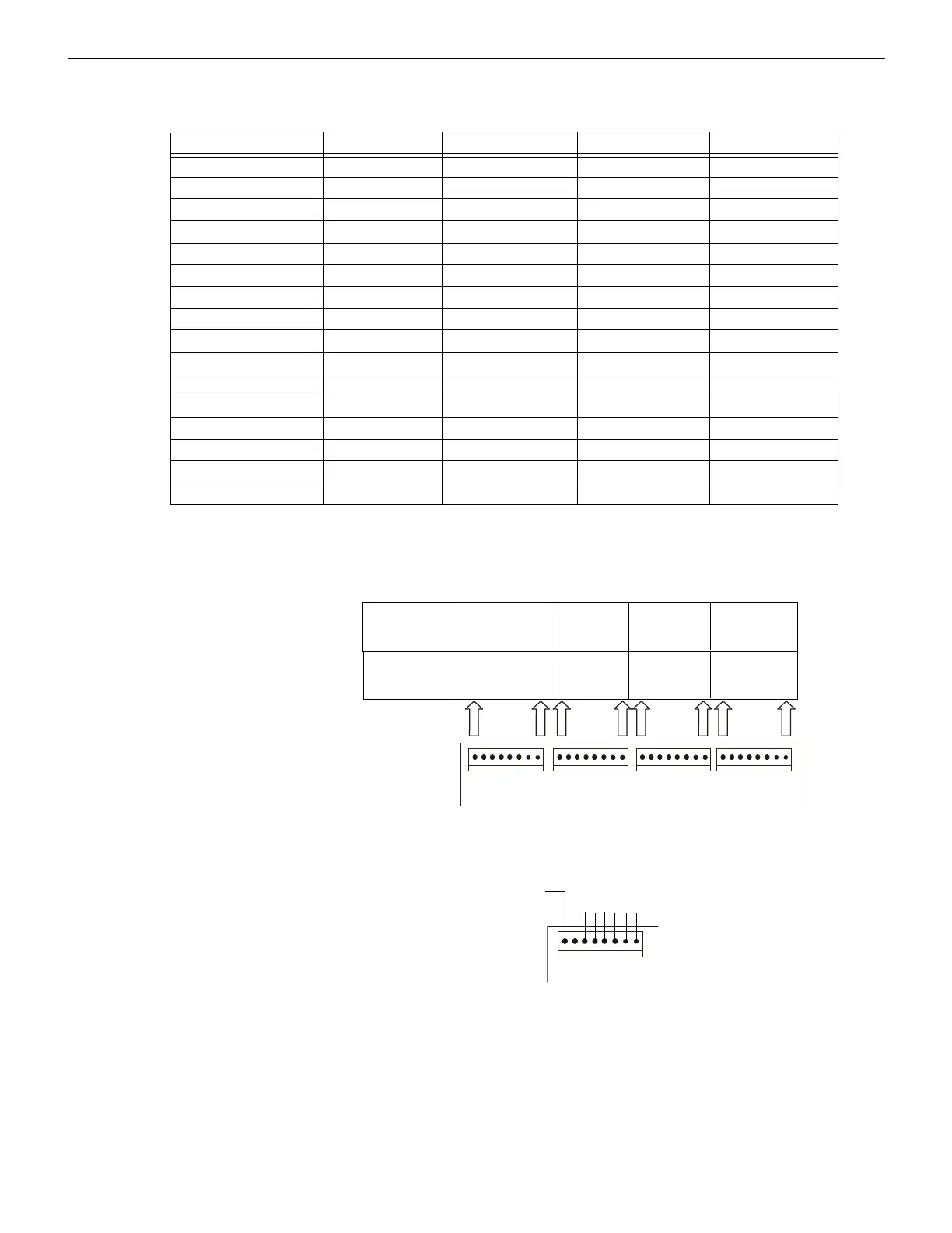
Figure E.1 illustrates configuration of the LDM to annunciate the Active state of all 99 software zones (no zone troubles) with the first
eight points (P1 through P8) dedicated to the AFP-200 system function LEDs listed below.
LDM Switch Position LDM-32 1st LDM-E32 2nd LDM-E32 3rd LDM-E32
1 not used not used not used not used
2 not used not used not used not used
3 not used not used not used not used
4 not used not used not used not used
5 not used not used not used not used
6 not used not used not used not used
7 not used not used not used not used
8 not used not used not used not used
9 not used not used not used ACK
10 not used not used not used SIG.SIL.
11 not used not used not used RESET
12 not used not used not used DRILL
13 not used not used not used not used
14 not used not used not used not used
15 not used not used not used not used
16 not used not used not used not used
Address #1
LDM-32
LDM-E32
System Functions *
25 - 32
1 - 8
33 - 40
9 - 16
41 - 48
17 - 24
49 - 56
Address #2
LDM-32
LDM-E32
57 - 64
89 - 96
65 - 72
97 - 99
73 - 80
81 - 88
* System Status Indicators
System Alarm
not used
View of LDM-32
wire to
LEDs
Figure E.1 Display Active Status of Software Zones Only
* It is assumed this mod-
ule/expander annunciates zones
65-99 and is not functioning as a
'Receive Only' annunciator.

 Loading...