LDM Series Instruction Manual — P/N 15885:H3 8/12/2019 63
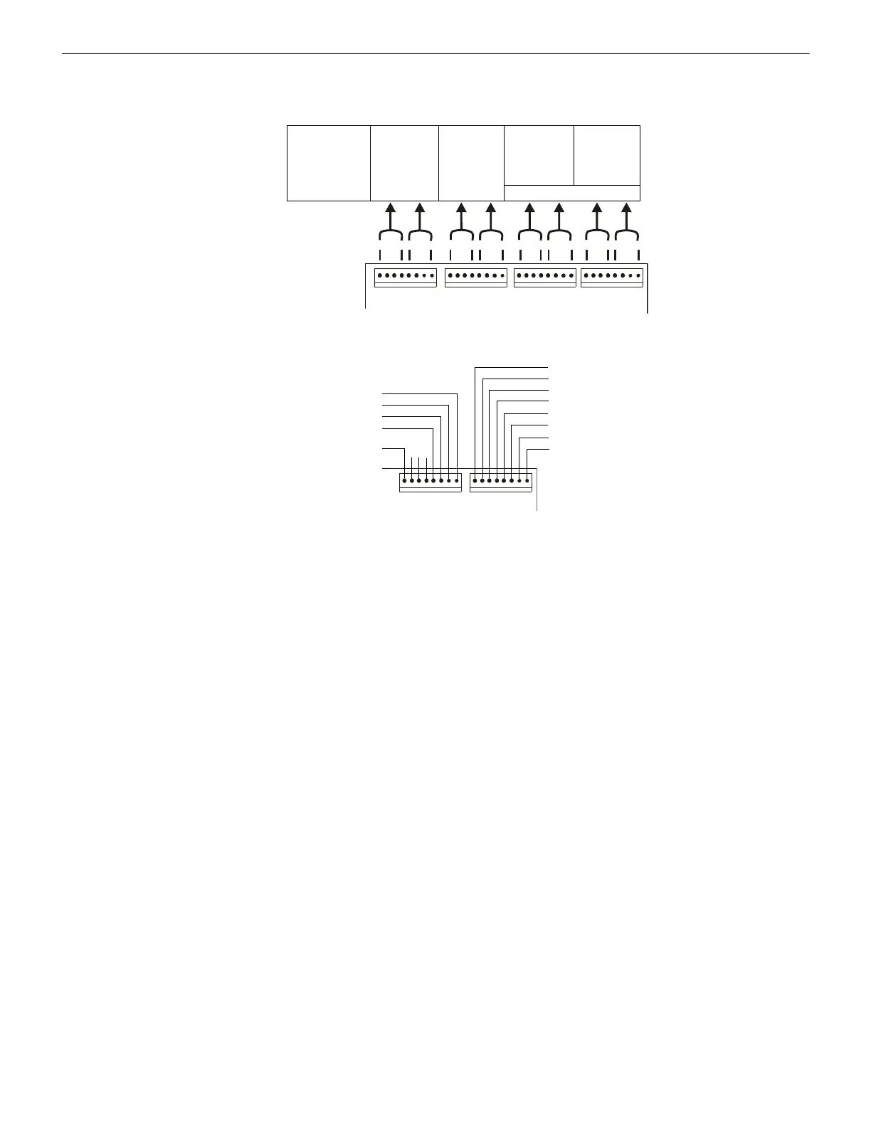
Configuration for the LDM-32 and AFP-200 AFP-200 (UL 8th)
Figure E.4 illustrates configuration for the LDM to annunciate active and trouble states for the first 56 software zones with the last eight
points (16 LEDs) dedicated to the AFP-200 functions listed below.
It is assumed that the '8-Point Shift' will be selected only on systems containing less than 56 circuits.
J6
J5 OUTPUTS J7
J8
Alarm
Alarm Alarm Alarm
Trouble
Tro ubl e Tro ub l e
Address #1
LDM-32
1st LDM-E32
2nd LDM-E32
3rd LDM-E32
System Status Indicators*
13 - 16
29 - 32
45 - 48
1 - 4
17 - 20
33 - 36
49 - 52
9 - 12
25 - 28
41 - 44
5 - 8
21 - 24
37 - 40
53 - 56
* System Status Indicators
View of LDM-32
not used
not used
not used
not used
Supervisory (Yellow LED)
Pre-Alarm
AC Fail (Yellow LED)
Panel Trouble
not used
not used
Signals Silenced (Yellow LED)
System Trouble (Yellow LED)
System Alarm (Red LED)
not
Figure E.4 Activation/Trouble Operation With 8-Point Shift

 Loading...