20
SPM Flex Gas Detector
Wiring and tubing
• The safety of any system incorporating the SPM Flex gas detector is
the responsibility of the assembler of the system�
• Position a permanently-installed SPM Flex gas detector so that it does
not interfere with access to the dedicated circuit breaker�
• Use only the specified power adaptor/charger (see “Specifications” on
page 63)�
• Use the power adaptor/charger only in indoor applications�
CAUTION
!
Do not wire relays and 4-20 mA in the same wire bundle�
NOTE
Typical fixed installation topologies
The SPM Flex gas detector has flexible installation options that allow the user to
select the one most suitable for a specific application� The detector is supplied
with weather-sealed connectors for power, Ethernet, and communications
(for relays or 4-20 mA)� The Ethernet port can be replaced with an appropriate
connection in accordance with local codes (allowing the user to wire directly to
the terminal block)� Install each detector near a dedicated circuit breaker�
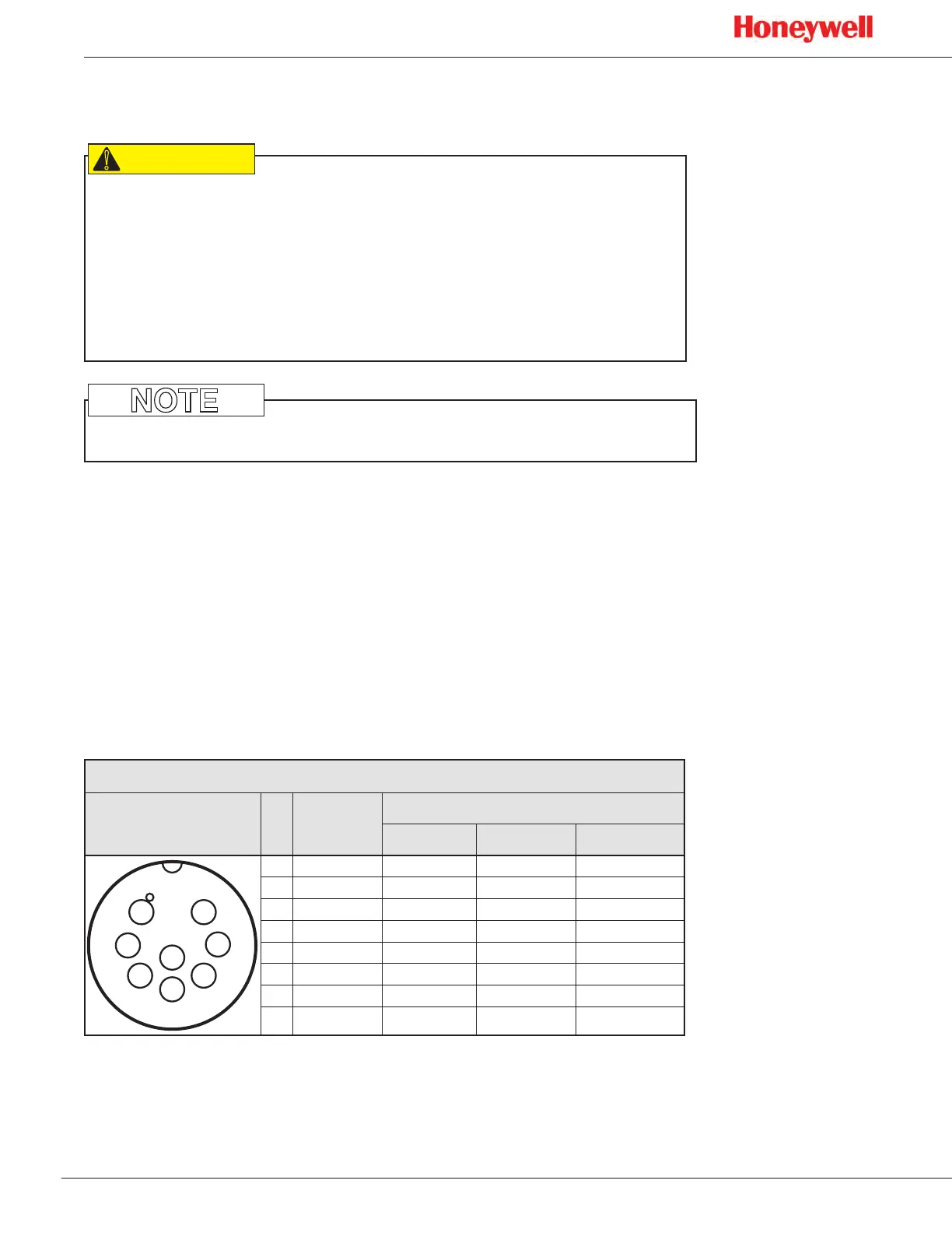
This table shows the default wiring configuration for the IP-rated communication
connector when installed by Honeywell Analytics� The relays are labeled for the
factory default but the configuration can be modified to have a single alarm and
separate faults�
Relay/mA Terminal Connections
Front View No. Color
Relay/mA Terminal Connections
mA Sink mA Source Isolated mA*
1
2
3
5
4
6
7
8
1 Red
Alarm2 NO Alarm2 NO Alarm2 NO
2 Black
Alarm2 COM Alarm2 COM Alarm2 COM
3 White
Alarm1 NO Alarm1 NO Alarm1 NO
4 Green
Alarm1 COM Alarm1 COM Alarm1 COM
5 Brown
Fault NO Fault NO Fault NO
6 Blue
Fault COM Fault COM Fault COM
7 Yellow
24 VDC + 4-20 mA - 4-20 mA -
8 White/Black
4-20 mA + 24 VDC - 4-20 mA +
*default pin configuration
Electrical connection is made via conduit directly to ports or via the connector
(see Figure 1, “Connectors and ports” on page 10� The terminals used are
suitable for conductors of 20 to 14 AWG (0�8 to 1�6 mm dia�)�

 Loading...