51
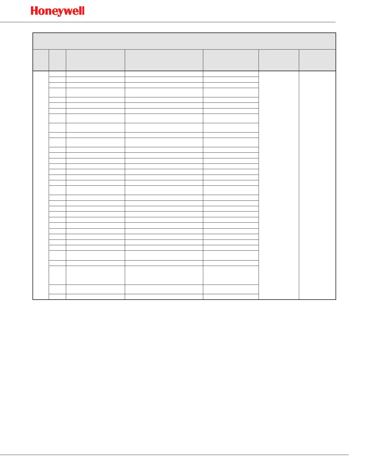
SPM Flex Gas Detector
Instrument Fault/Maintenance Fault/Information Codes
Type
Sub-
type
Display
String
Technical
Description
Meaning of
Parameter
Probable
Cause
Corrective
Action
Information
1 SPM Energized The microprocessor booted N/A
N/A N/A
2 Monitoring Started Monitoring started N/A
N/A N/A
3 Monitoring Stopped Monitoring stopped N/A
N/A N/A
4 Tape Advanced
A new windows was pulled� (remove for
production)
N/A
N/A N/A
5 Force mA Requested zero
N/A Start force relay
6 mA Output Forced current loop forcing started zero
N/A N/A
7 mA Output Released current loop forcing ended� N/A
N/A N/A
8 User Login User logged-in successful�
User level which just logged in, 0
is lowest level
N/A N/A
9 User Logged Out User logged out manually or by timeout�
User level which just logged out,
0 is lowest level
N/A N/A
10 Alarm/Fault Reset Request UI requests alarm/fault reset� N/A
N/A N/A
11 Silent Buzzer Request
UI requests to shut off buzzer through Alarm/
fault reset menu�
N/A
N/A N/A
12 Enter Monitor Request� UI requests to enter monitor N/A
N/A N/A
13 Exit Monitor Request UI requests to out of monitor N/A
N/A N/A
14 Change CC Started UI initialize change CC sequence N/A
N/A N/A
15 Inhibit Started UI initializes inhibit� which type of inhibit�
N/A N/A
16 Inhibit End Request UI request to end inhibit� N/A
N/A N/A
17 4-20mA Calibration Started UI initializes 4-20 calibration� N/A
N/A N/A
18 Flow Characterization Started UI initializes flow char N/A
N/A N/A
19 Update Program Started
User chose an update file to perform program
update�
N/A
N/A N/A
20 Update Program Failed Update program failed N/A
N/A N/A
21 Update Program Success Update program success N/A
N/A N/A
22 Gas Related Configuration� Gas related set up changed by UI� N/A
N/A N/A
23 Non Gas Related Configuration� Non-gas set up changed by UI� N/A
N/A N/A
24 Security Set Up Configuration Security set up changed N/A
N/A N/A
25 Optics Verification Started UI initialized optics verification sequence N/A
N/A N/A
26 Simulation Started UI requests to start simulation� N/A
N/A N/A
27 Force Relay Started UI started force relay� N/A
N/A N/A
28 Force Relay End Request UI exited force relay function� N/A
N/A N/A
29 Time Changed UI time set N/A
N/A N/A
30 Optics Auto Adjust Requested N/A
N/A
Start optics auto-
adjust
31 Optics Auto Adjust Success Optics Auto-Adjust Success� LED drive counts
N/A N/A
32 Optics Corrected LED output dropped unexpectedly
1 – first SLDE
2 – second SLDE
3 – Reference Photodiode Shift
N/A N/A
33 Mfg Service Mode
UI has received commands to go into
manufacturing service mode
None
N/A N/A
34 Electrical Noise Optics block reports signal is noisy Failure code
N/A N/A

 Loading...