TC · Edition 08.17 11
Application
1.1.5
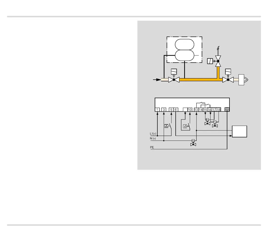
TC 2 with two gas solenoid valves and one auxiliary
valve for discharge
Mains voltage = control voltage
V1: quick or slow opening valve with start rate.
V2: any.
V3: quick opening, nominal size is dependent on test
volume V
P
and inlet pressure p
u
, see page 38 (Pro-
ject planning information), but is at least DN 15.
TC 2 checks gas solenoid valves V1, V2, the auxiliary
valve V3 and the pipe between the valves for tightness.
If all the gas solenoid valves are tight, the tightness
control forwards the OK enable signal to the automatic
burner control unit GFA. The GFA opens the gas so-
lenoid valves V1 and V2 simultaneously. The burner
starts.
A relief line is used to discharge the test volume V
P
into
a safe area. Thanks to the installed auxiliary valve V3,
valve V2 can also be a slow opening motorized valve VK.
p
u
2
V1
V2
PZ
p
u
p
z
TC 2
V3
V
P
GFA
V1
TC 2
OK
9
V3
V2

 Loading...