EasyManua.ls Logo

Honeywell TC Series User Manual

Honeywell TC Series
55 pages
To Next Page IconTo Next Page
To Previous Page IconTo Previous Page
Page #13 background image
TC · Edition 08.17 13
Application
1.1.7
TC 3 in a multiple burner system with several valves
installed in series
V1 and V2: any.
TC 3 checks slow opening main valves V1 and V2 and
the pipe between these valves for tightness.
The test volume V
P
is supplied and discharged via the
TC 3 auxiliary valves.
Valve V2 can only be checked for tightness when the
pressure downstream of V2 approximately corresponds
to the atmospheric pressure and the volume down-
stream of valve V2 is 5 x V
P
. The gas solenoid valve VAS
and the pressure switch DG
VAS
are used to relieve the
pressure. The pressure switch must be adjusted in such
a way so that enough pressure is relieved and no air can
get into the pipework.
Once the tightness test has been carried out success-
fully, TC 3 opens the main valves V1 and V2 with the
OK enable signal and enables the downstream burner
control units.
K1
DG
VAS
VAS
VAS
DG
VAS
PZ
TC 3
OK
9
V1 V2
p
u
p
z
V
P
PZ
TC 3
p
u
2
p
u
p
d
K1
V1
V2

Table of Contents

Question and Answer IconNeed help?

Do you have a question about the Honeywell TC Series and is the answer not in the manual?

Honeywell TC Series Specifications

General IconGeneral
CategoryControl Unit
Enclosure RatingIP20
Input Voltage24 VDC
Communication ProtocolModbus RTU, BACnet MS/TP
SeriesTC Series

Summary

Tightness Controls TC

1 Application

TC Model Application Overview

Details on application examples for TC 1V, TC 1C, TC 1, TC 2, TC 3, and TC 4 models.

2 Certification

TC 1, TC 2, TC 3 Certifications

Certifications for TC 1, TC 2, and TC 3 models, including SIL and PL.

TC 4 Certifications

Certifications for TC 4 model, including UL, FM, AGA, CE.

3 Function

TC 1, TC 2, TC 3 Functionality

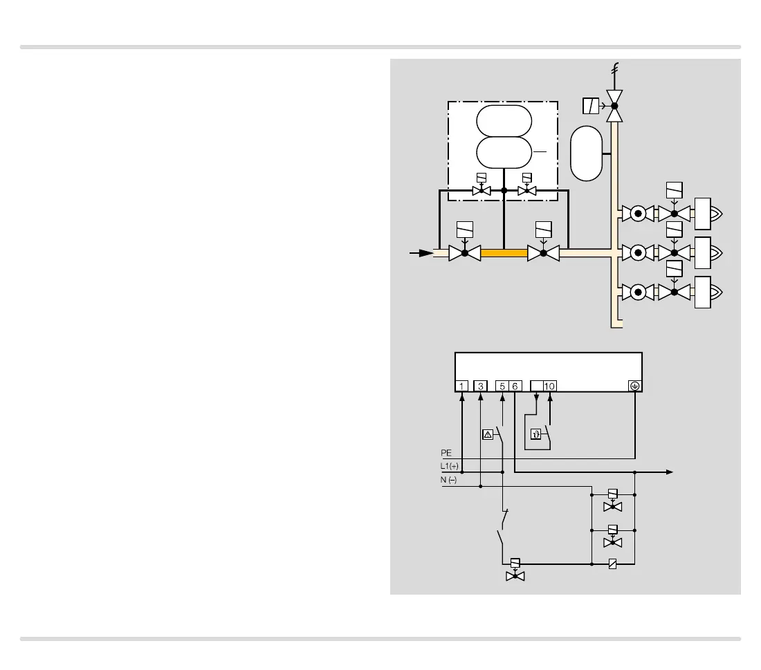
Functionality, connection diagrams, and test procedures for TC 1, TC 2, TC 3.

TC 4 Functionality

Functionality, connection diagrams, and test procedures for TC 4.

4 Selection

TC 1, TC 2, TC 3 Selection

Selection tables and type codes for TC 1, TC 2, TC 3 models.

TC 4 Selection

Selection tables and type codes for TC 4 model.

5 Project Planning Information

Auxiliary Valves and Start Rate

Guidelines for selecting auxiliary valves and minimum start rate for slow opening valves.

Installation and Electrical Connections

Instructions for installing TC units and their electrical connections.

Relief Line Sizing

Guidelines for determining the correct size for relief lines.

6 Accessories

Sockets and Cables

Details on standard sockets and valve connection cables.

External Pressure Switch for TC 4

Details on pressure switches DG, DG..C for TC 4 and their adjustment.

7 Technical Data

TC 1, TC 2, TC 3 Data

Electrical, environmental, and mechanical data for TC 1, TC 2, TC 3.

TC 4 Data

Electrical, mechanical, and environmental data for TC 4.

Indicators, Dimensions, and Conversions

Operating controls, dimensions, and unit conversion information.

Safety Characteristic Values

Safety characteristic values like SIL, PL, DC, PFHD for TC 1, TC 2, TC 3.

8 Safety Information (EN 61508-2)

General Safety Aspects

General safety, type of action, operating mode, and classifications for TC 1, TC 2, TC 3.

Interfaces and Connections

Electrical wiring, terminals, inputs, and outputs for TC 1, TC 2, TC 3.

SIL and PL Levels

Safety Integrity Level (SIL) and Performance Level (PL) for TC 1, TC 2, TC 3.

9 Maintenance Cycles

10 Glossary

Key Term Definitions

Definitions for terms like Tightness Control, VPS, Safety Interlocks, DC, PFHD, MTTFd.

Contact Information

Related product manuals