EasyManuals Logo
Home>Honeywell>Control Unit>TC Series

Honeywell TC Series User Manual

Honeywell TC Series
55 pages
To Next Page IconTo Next Page
To Previous Page IconTo Previous Page
Page #28 background imageLoading...
Page #28 background image
TC · Edition 08.17 28
Function
3.2 TC 4
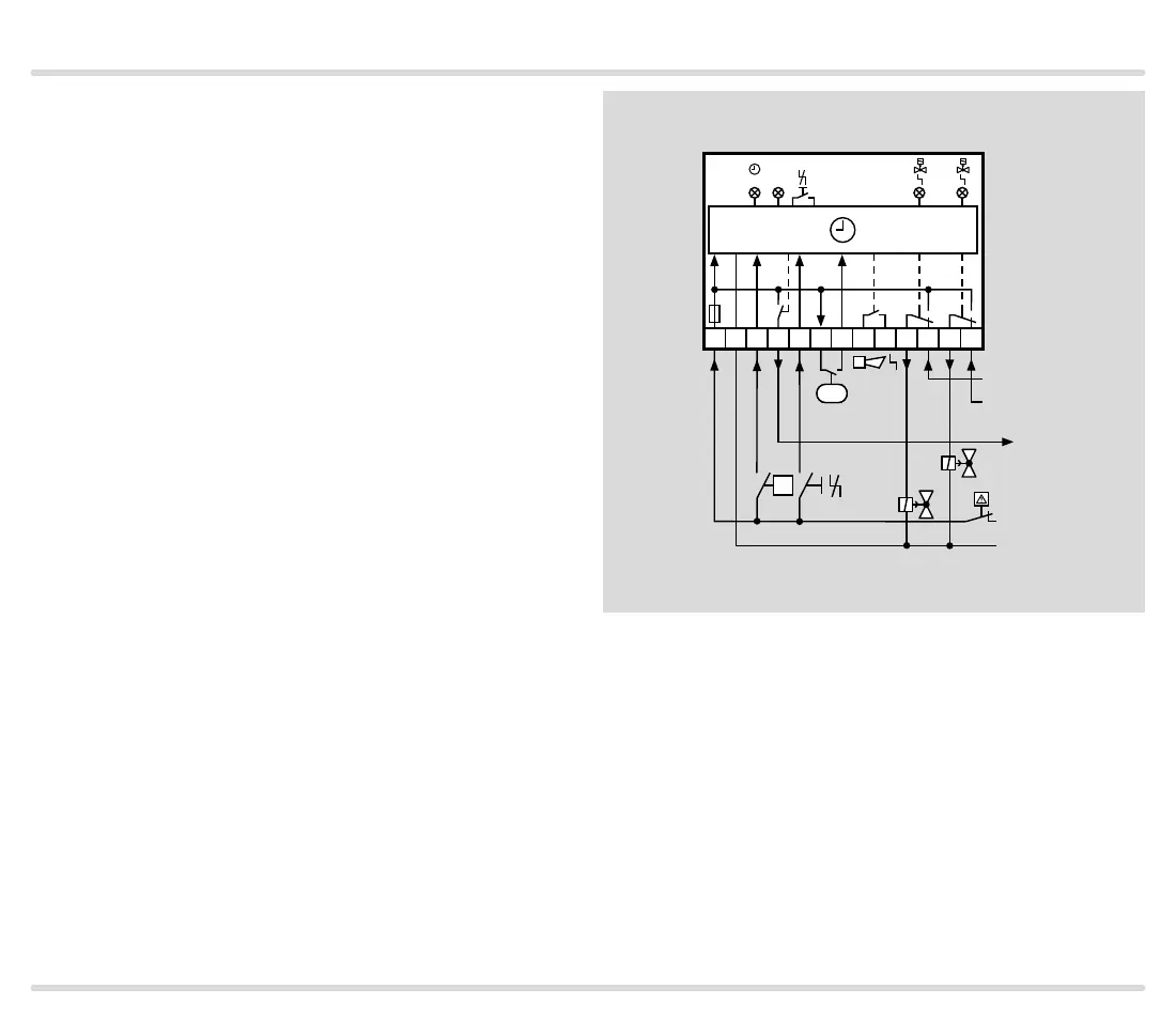
3.2.1 Connection diagram
Fault signalling contact on terminals 8 and 9: signalling
contact (not internally fused), max. 1 A for 220/240 V
(high voltage: 264 V), max. 2 A for 120 V.
Connect the NO contact on the pressure switch to ter-
minals 6 and 7.
1 2 3 4 5 6 7 8 9 10 11 12 13
L1(+)
V1
L1(+)
V2
OK
max. 1 A,
264 V
ϑ
L1(+)
N(-)
p
u
/2
5 AT
TEST OK
V1
1 2
V2
PZ

Table of Contents

Questions and Answers:

Question and Answer IconNeed help?

Do you have a question about the Honeywell TC Series and is the answer not in the manual?

Honeywell TC Series Specifications

General IconGeneral
BrandHoneywell
ModelTC Series
CategoryControl Unit
LanguageEnglish

Related product manuals