TC · Edition 08.17 27
Function
3.1.8 Measurement time t
M
for TC 1, TC 2, TC 3
The sensitivity of the tightness control TC can be ad-
justed by adapting the measurement time t
M
for each
individual system. The longer the measurement time t
M
,
the greater the sensitivity of the tightness control. The
longer the measurement time, the smaller the leakage
rate at which a safety shut-down/fault lock-out is trig-
gered.
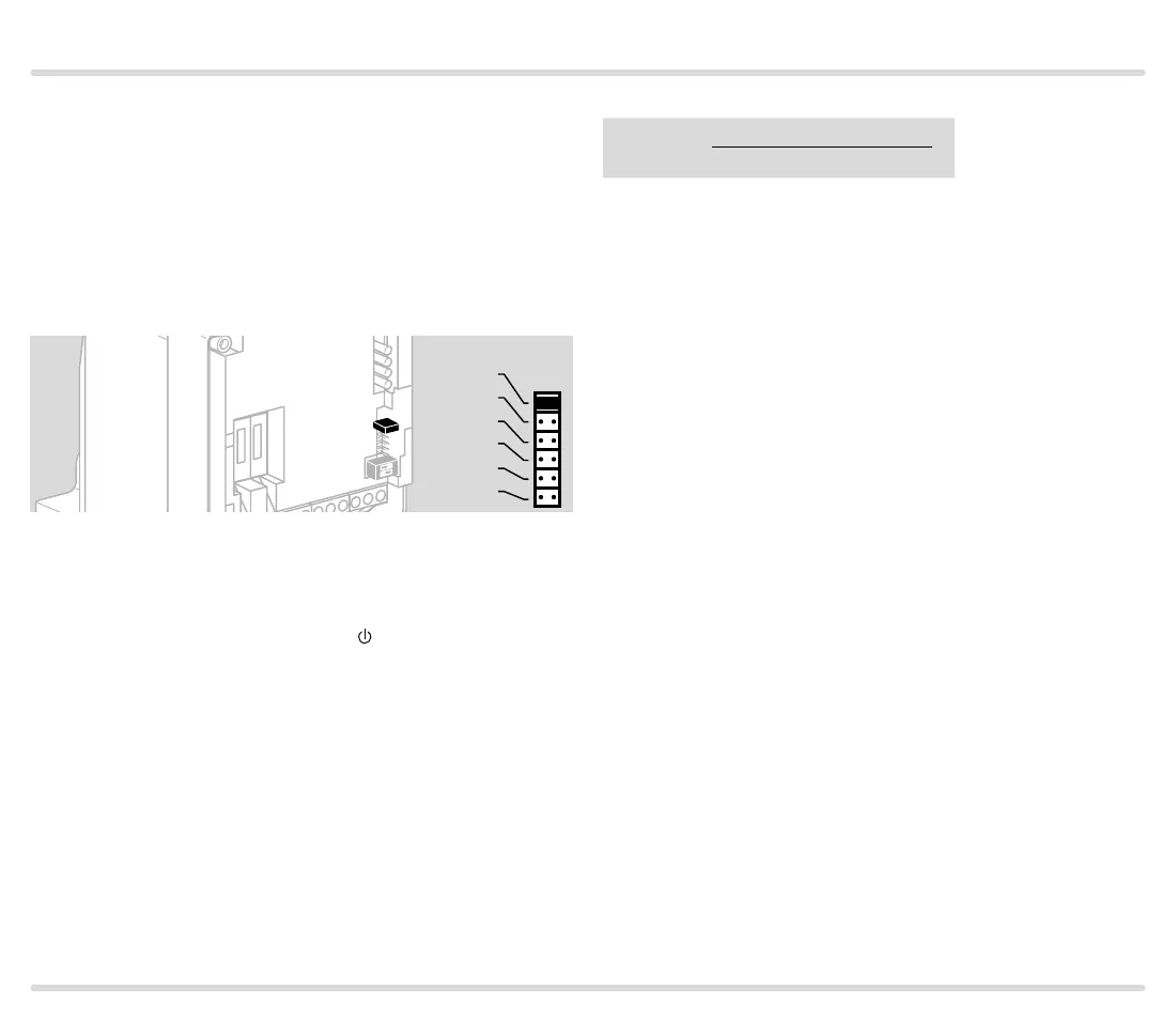
M
5s
10s
15s
20s
25s
30s
The measurement time can be set with a jumper to be-
tween 5 s and max. 30 s.
30 s = factory setting
Without jumper: no function. The
LED is permanently
red.
The required measurement time t
M
is calculated from:
Q
max.
= max. flow rate [m
3
/h]
Q
L
= leakage rate [l/h] = Q
max.
[m
3
/h] x 0.1%, see
page 35 (Leakage rate Q
L
)
p
u
= inlet pressure [mbar]
V
P
= test volume [l], see page 34 (Test volume V
P
for TC 1, TC 2, TC 3, TC 4)
Converting units, see www.adlatus.org.
Measurement time t
M
t
M
[s] =
2.5 x p
u
[mbar] x V
P
[l]
Q
L
[l /h]
For all combination controls CG, the measurement
time t
M
for TC 1C is 5 s.
Test period t
P
The entire test period is calculated from the measure-
ment time t
M
for both valves and the fixed opening
time t
L
of both valves.
t
P
[s] = 2 x t
L
+ 2 x t
M
3.1.9 Calculation example for t
M
See Calculating measurement time t
M
of tightness
controls TC 1, TC 2, TC 3.

 Loading...