TC · Edition 08.17 40
Project planning information
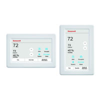
5.3.3 TC 2
An adapter plate is supplied for mounting the TC 2 to a
gas solenoid valve.
TC 2..R: Rp ¼
TC 2..N: ¼ NPT
p
u
z
We recommend using Ermeto screw couplings to at-
tach the adapter plate to the gas solenoid valve.
The connections for p
u
and p
z
are marked on the adapt-
er plate.
p
u
p
z
p
z
p
u
p
z
5.3.4 TC 3
Connect the TC to the inlet pressure connection p
u
, the
intermediate pressure connection p
z
and the outlet
pressure connection p
d
of the inlet valve. Use a 12 x 1.5
or 8 x 1 pipe for the pipe connections.
p
z
p
d
p
z
p
u
TC 3..R: Rp ¼
TC 3..N: ¼ NPT
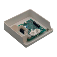
5.3.5 TC 4
On the TC 4, the external pressure switch is mounted
on the interspace between the valves to be monitored.
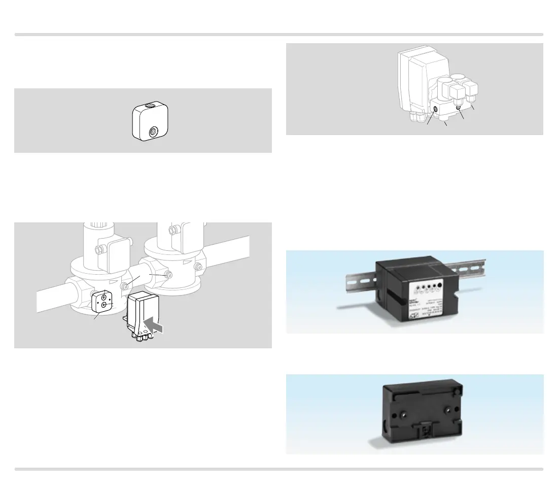
The TC can be installed separately from the valves. For
installation in the control cabinet housing, for example,
the lower section can be secured with screws or
mounted on a DIN rail.
Snap attachment for DIN rail of 35 mm (1.36 inch) in
width.

 Loading...