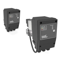
TC · Edition 08.17 50
Safety information in accordance with EN 61508-2 for TC 1, TC 2, TC 3
8.2 Interfaces
8.2.1 Electrical wiring
Attachment type X to EN 607301.
230 V AC, 120 V AC
Connection:
The TC 1, TC 2, TC 3 must be correctly phased in ac-
cordance with the connection diagrams.
24 V DC
Extra-low voltage (ELV):
If the TC 1, TC 2, TC 3 is supplied with ELV, at which Mi-
nus/-/GND are connected to PE, all connected cables
must not be longer than 10 m.
If the TC 1, TC 2, TC 3 is supplied with ELV, at which
Minus/-/GND are not connected to PE, all connected
cables may be longer than 10 m.
Safety extra-low voltage (SELV):
If the TC 1, TC 2, TC 3 is supplied with SELV, all con-
nected components must also fulfil the requirements
of SELV.
Protected extra low voltage (PELV):
If the TC 1, TC 2, TC 3 is supplied with PELV, all con-
nected cables must not be longer than 10 m.
8.2.2 Connection terminals
Supply and control signal terminals
Mains voltage = control voltage 24 V DC,
120 V AC or 230 V AC: power is supplied to the TC via
connection terminals 1 (L1 (+)) and 3 (N (-)). Further
terminal assignment, see connection diagrams.
120 V AC or 230 V AC mains voltage,
24 V DC control voltage: control voltage is supplied via
connection terminals 8 (+) and 9 (-).
Terminals for automatic burner control unit and
valves
See connection diagrams.
PE wire connection
5 PE terminals for forwarding. Connection to the sys-
tem PE must be carried out/wired by the user.
8.2.3 Inputs
Safety interlocks (limits)
Input voltage = mains voltage
Thermostat/start-up signal ϑ
Input voltage = control voltage
Reset/remote reset
Input voltage = control voltage
 Loading...
