TC · Edition 08.17 15
Application
1.1.9
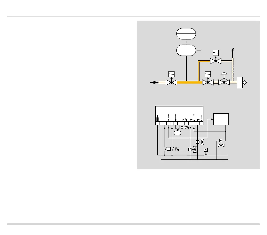
TC 4 with two gas solenoid valves and one auxiliary
valve for discharge
V1: quick or slow opening valve with start rate.
V2: any.
V3: quick opening, nominal size is dependent on test
volume V
P
and inlet pressure p
u
, see page 38
(Project planning information), but is at least DN 15.
TC 4 checks gas solenoid valves V1, V2, the auxiliary
valve V3 and the pipe between the valves for tightness.
It must be ensured that the interspace p
z
is vented dur-
ing the 2-second opening time. This is not guaranteed
by the gas pressure regulator downstream of V2. A relief
line is thus used to discharge the test volume V
P
safely
into the combustion chamber or into a safe area. Since
valve V2 remains closed during the test, it can also be a
slow opening motorized valve VK.
If all the gas solenoid valves are tight, TC 4 forwards
the OK enable signal to the automatic burner control
unit GFA. The GFA opens the gas solenoid valves V1
and V2 simultaneously. The burner starts.
1 2 3
4
5 6 7 8 9 10 11 12 13
OK
L1(+)
N(-)
TC 4
V1
V3
V2
V1 V2
p
u
p
z
V3
p
u
2
PZ
DG
TC 4
ϑ
V
P
PZ
GFA

 Loading...