TC · Edition 08.17 12
Application
1.1.6
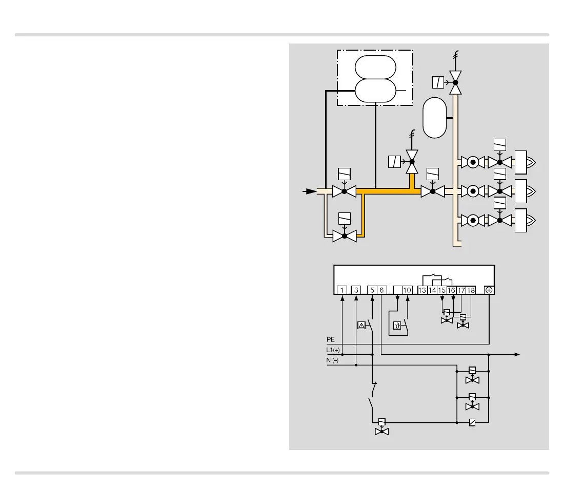
TC 2 in a multiple burner system with several valves
installed in series
Mains voltage = control voltage
V3 and V4: quick opening, nominal size is dependent
on test volume V
P
and inlet pressure p
u
, see page 38
(Project planning information), but is at least DN 15.
When using slow opening main valves (V1 and V2), aux-
iliary valves (V3 and V4) must be used for the supply
and discharge of the test volume V
P
.
TC 2 checks the central shut-off valve V1, the gas so-
lenoid valve V2, the auxiliary valves V3 and V4 and the
pipe between these valves for tightness.
Valve V2 can only be checked for tightness when the
pressure downstream of V2 approximately corresponds
to the atmospheric pressure and the volume down-
stream of valve V2 is 5 x V
P
. The gas solenoid valve VAS
and the pressure switch DG
VAS
are used to relieve the
pressure. The pressure switch must be adjusted in such
a way so that enough pressure is relieved and no air can
get into the pipework.
Once the tightness test has been carried out success-
fully, TC 2 opens the main valves V1 and V2 with the
OK enable signal and enables the downstream burner
control units.
V4
V3
p
u
2
V1 V2
PZ
p
u
p
z
TC 2
K1
DG
VAS
VAS
V3
V4
VAS
DG
VAS
PZ
V
P
TC 2
OK
K1
V1
V2
9

 Loading...