TC · Edition 08.17 31
Function
3.2.3 TC 4 test instant
A jumper (on the left in the picture) is used to determine
whether the tightness of the gas solenoid valves is to be
checked before or after burner run.
The test period t
P
is set using the second jumper (on the
right in the picture), see page 33 (Test period t
P
for
TC 4).
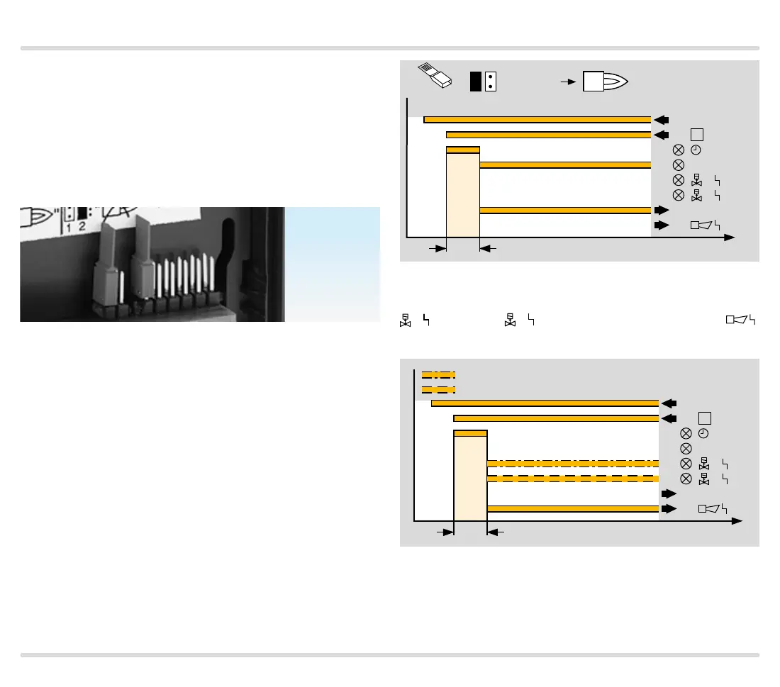
3.2.4
Test instant for Mode 1: testing before burner run
Mode 1 = factory setting.
Mains voltage L1 is switched on. The tightness test
starts with incomingthermostat/start-up signal ϑ. If the
valves are tight, the green OK LED lights up. The OK en-
able signal is forwarded to the automatic burner control
unit.
t
p
ϑ
TEST
OK
1
2
OK
1 2
Mode
L1
(+)
1
5
6
7
t
"TEST: "
If the tightness control TC detects a leak on one of the
two valves, the red LED lights up for a fault on valve V1
or valve V2
. A fault is signalled externally ,
e.g. by switching on a buzzer or a warning light.
L1
(+)
ϑ
TEST
OK
OK
t
1
5
6
7
t
p
1
2
V1 leaking
V2 leaking

 Loading...