TC · Edition 08.17 20
Function
3 Function
3.1 TC 1, TC 2, TC 3
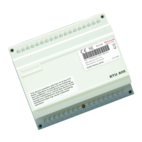
3.1.1 Connection diagrams for TC 1, TC 2
TC 1..W/W, TC 1..Q/Q, TC 1..K/K,
TC 2..W/W, TC 2..Q/Q or TC 2..K/K
Mains voltage = control voltage
24 V DC, 120 V AC or 230 V AC,
see page 37 (Selection).
OK
V2
TC 1, TC 2
V1
V1 = inlet valve, V2 = outlet valve.
Remote reset by applying control voltage to terminal 11
or via a floating contact between terminals 8 and 11.
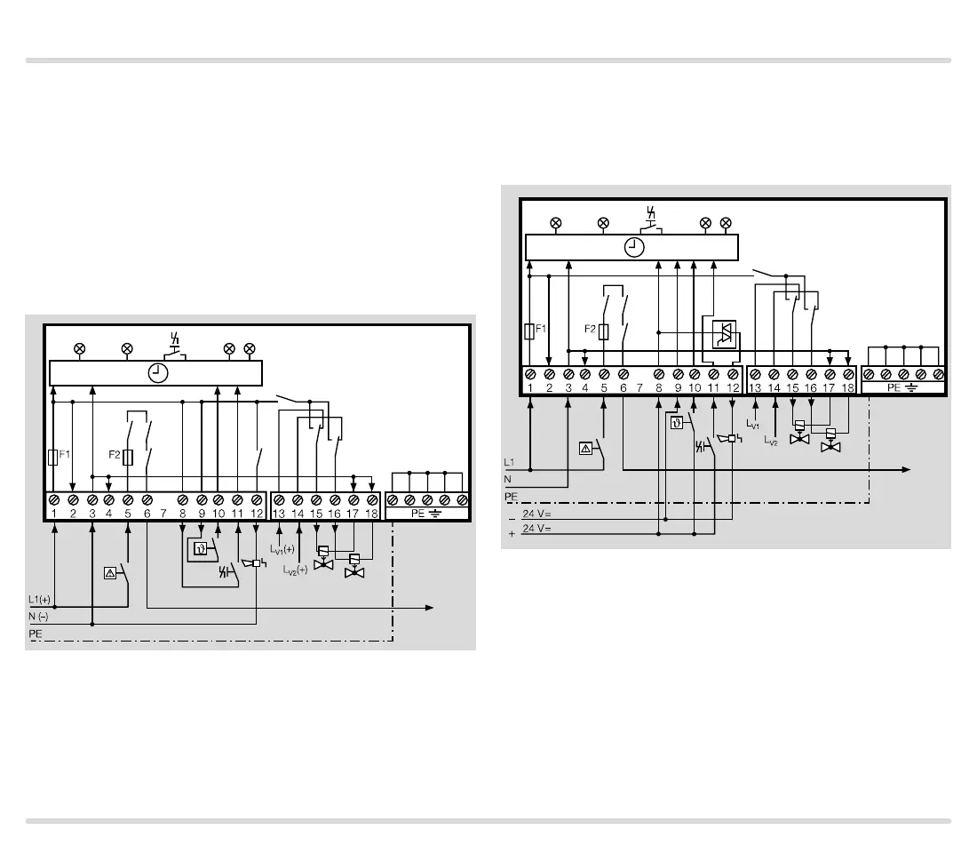
TC 1..W/K, TC 1..Q/K, TC 2..W/K or TC 2..Q/K
Mains voltage: 120 V AC or 230 V AC
Control voltage: 24 V DC,
see page 37 (Selection).
TC 1, TC 2
V2
V1
OK
V1 = inlet valve, V2 = outlet valve.
Remote reset by applying control voltage (+24 V) to ter-
minal 11.

 Loading...