General Description
MAN0996_Iss 1_02/16 Touchpoint Plus
Pt. No. 3011M5044_EN 19 User Guide
3.3.2 TPPL Expansion Unit
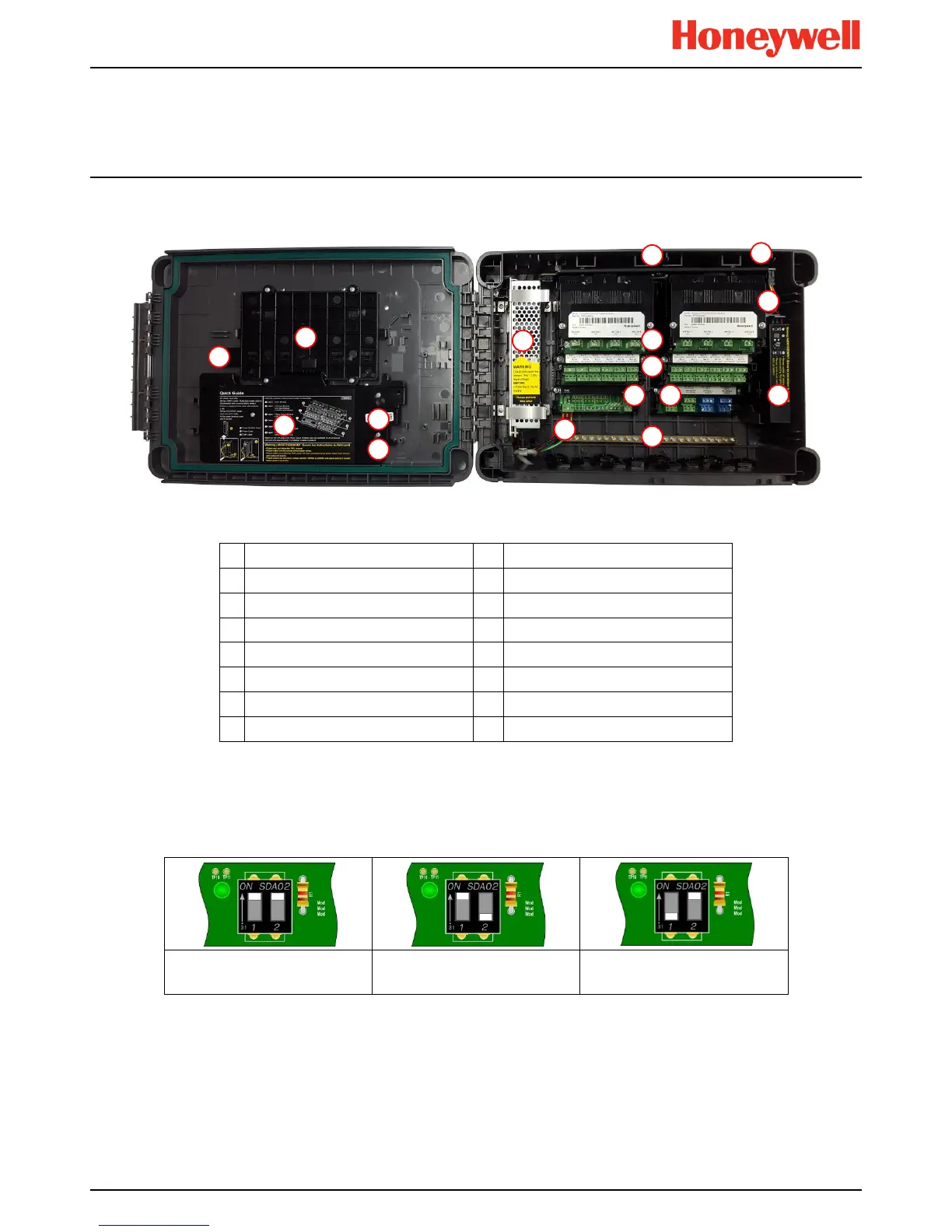
This figure shows the building blocks of the Touchpoint Plus Expansion Unit.
Figure 11. Expansion Unit Layout Before Installation
1
No Touchscreen
9
Battery Connector
2
No SD Card
10
mA Output Modules
3
No Motherboard
11
Relay Output Modules
4
No Modbus Terminals
12
Main Module (Power and CAN only)
5
No Ethernet Connector
13
Input Module (Dual shown)
6
Switched Mode Power Supply
14
Backup Battery
7
DIP Switch (on backplane)*
15
Power Terminal
8
Battery On / Off Switch
16
Earth (Ground) Bus Bar
3.3.3 TPPL DIP Switches
TPPL Backplanes have a DIP switch (item 14 in the figures above) that controls the interaction between the master (basic)
and the optional expansion unit backplanes. Once set these DIP switches need not be altered.
Basic Unit
Both On
Basic Unit with Slave
1 On, 2 Off
Expansion Unit
1 Off, 2 On
Figure 12. Backplane DIP Switch Settings

 Loading...


