Maintenance
MAN0996_Iss 1_02/16 Touchpoint Plus
Pt. No. 3011M5044_EN 48 User Guide
5) Touch [Apply].
6) Check the appropriate mA output levels using a suitable ammeter.
7) Repeat steps 4 to 6 for all mA output channels.
8) Touch [Finish] when the tests are completed.
6.2.4 Calibrating mV Input Channels
Catalytic sensors should be calibrated periodically according to the manufacturer’s recommendations. This should be a
two-person job to avoid the controller timing out and losing the settings.
Note: To enable a calibration interval for the channel, edit the interval setting before starting calibration (see the TPPL
Technical Handbook or call your Service Contact).
You should select First Span only when calibrating a new or replacement sensor for the first time. You then adjust the mV
Baseline, and then you should use Span for all calibrations thereafter (see Note below).
Note: Adjustment of the Baseline is only required when a mV channel is configured for the first time or when a catalytic
bead element is replaced. Once the Baseline is established it should not be adjusted for second or subsequent gas
calibrations, i.e. until the next catalytic bead replacement.
To Calibrate a mV Input Channel:
1) Install or replace catalytic bead sensor elements according to their technical manual.
2) Login as Administrator or Service.
3) Touch Menu>Maintenance>Adjust mV Baseline and select a mV input channel.
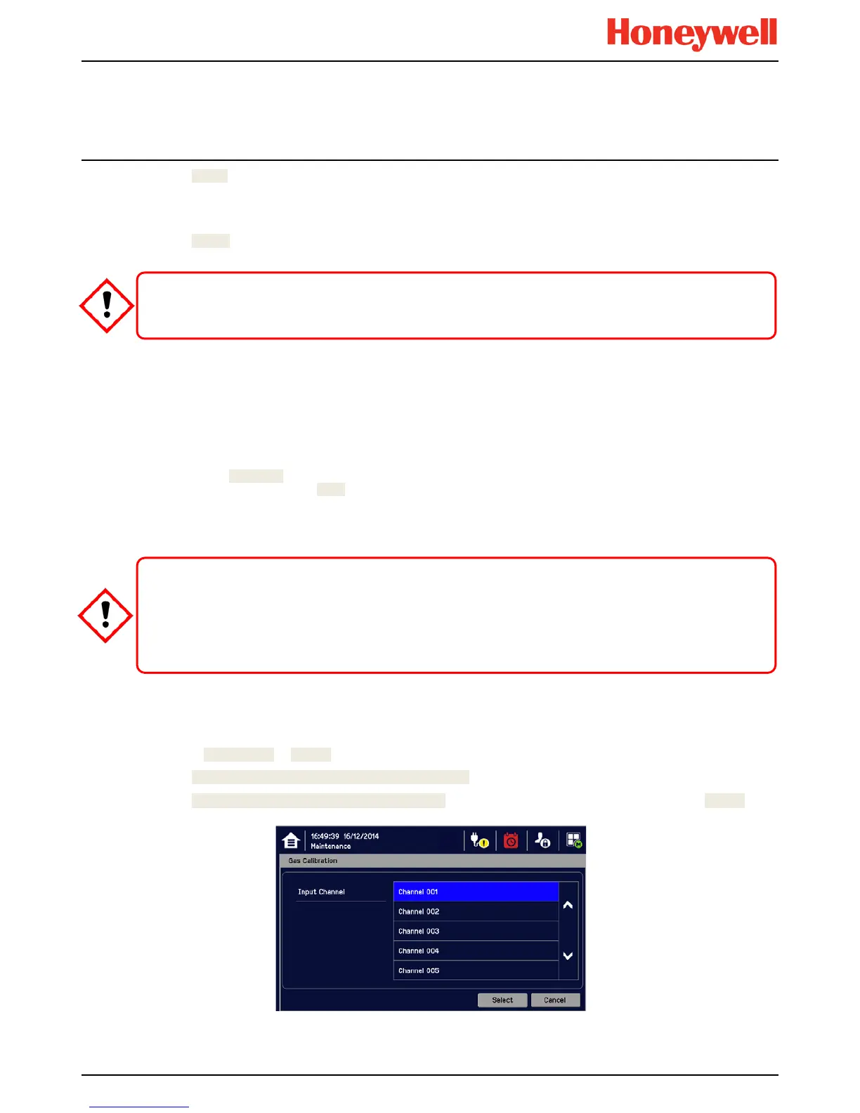
4) Touch Menu>Maintenance>Gas Calibration. Touch the channel to be calibrated, followed by [Select]:
CAUTION
Ensure that the system is returned to normal operation once testing is complete.
CAUTION
For greater accuracy, catalytic gas detectors should be calibrated using a certified gas/air mixture
equal to 50 %LEL of the actual target gas being monitored. Always refer to the sensor technical manual for
detailed information.
If you cannot obtain an exact or certified span gas match you can carry out a ‘cross-calibration’ using a similar

 Loading...


