XNX Universal Transmitter Quick Start Guide
11
4 Wiring the XNX transmitter
Personality circuit boards determine the XNX behavior based on the sensor type
attached to the XNX interface.
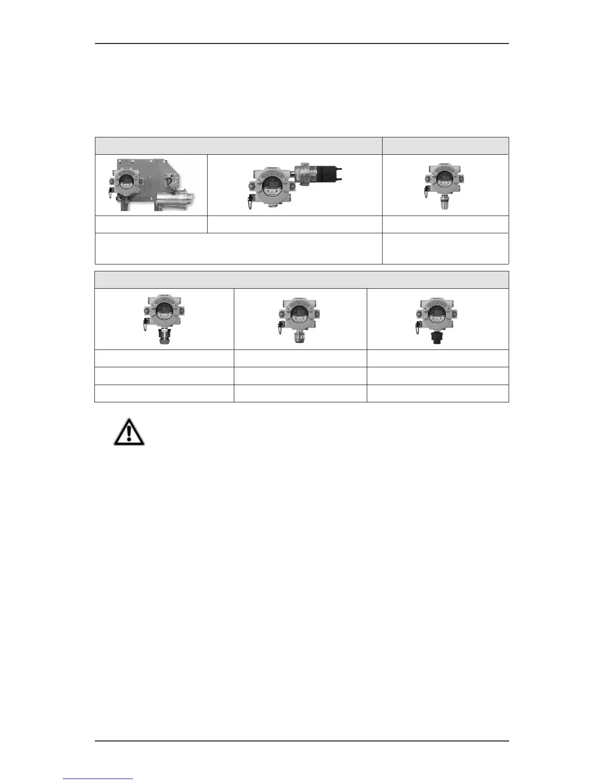
The table below defines the three XNX transmitter configurations and the sensors
each support.
XNX IR Personality XNX EC Personality
Searchline Excel Searchpoint Optima Plus Local/Remote XNX EC Sensor
Generic mA Sensors
XNX EC Sensor Remote
Mount Kit
XNX mV Personality
705 Local / Remote MPD Local (cat bead and IR) Sensepoint Local / Remote
705HT Local / Remote MPD Remote Sensepoint PPM Local/Remote
Sensepoint HT Remote
CAUTION
Before wiring the transmitter, conrm that the correct personality boards and options are installed.
4.1 General Wiring Considerations
For proper operation of the XNX Universal Transmitter and Sensor Technologies,
consideration of wiring induced voltage drops, transient electrical noise and
dissimilar Earth ground potentials is imperative in the design and installation of
the system.
NOTE:
EMI note for applications using shielded cable: Cable shield must provide 90%
coverage of the wiring. Cable shield terminations must be made at the cable
glands with suitable EMI-type glands. Avoid terminating cable shields at the Earth
ground lug inside the XNX enclosure. Where wiring is in pipe, a shielded cable is
not required.
Loading
Wiring for DC Power, 4-20mA Signal, remote wiring to sensors must be sized
sufficiently to provide sufficient voltages for the line length and the loads that will
be used.

 Loading...


