XNX Universal Transmitter Quick Start Guide
38
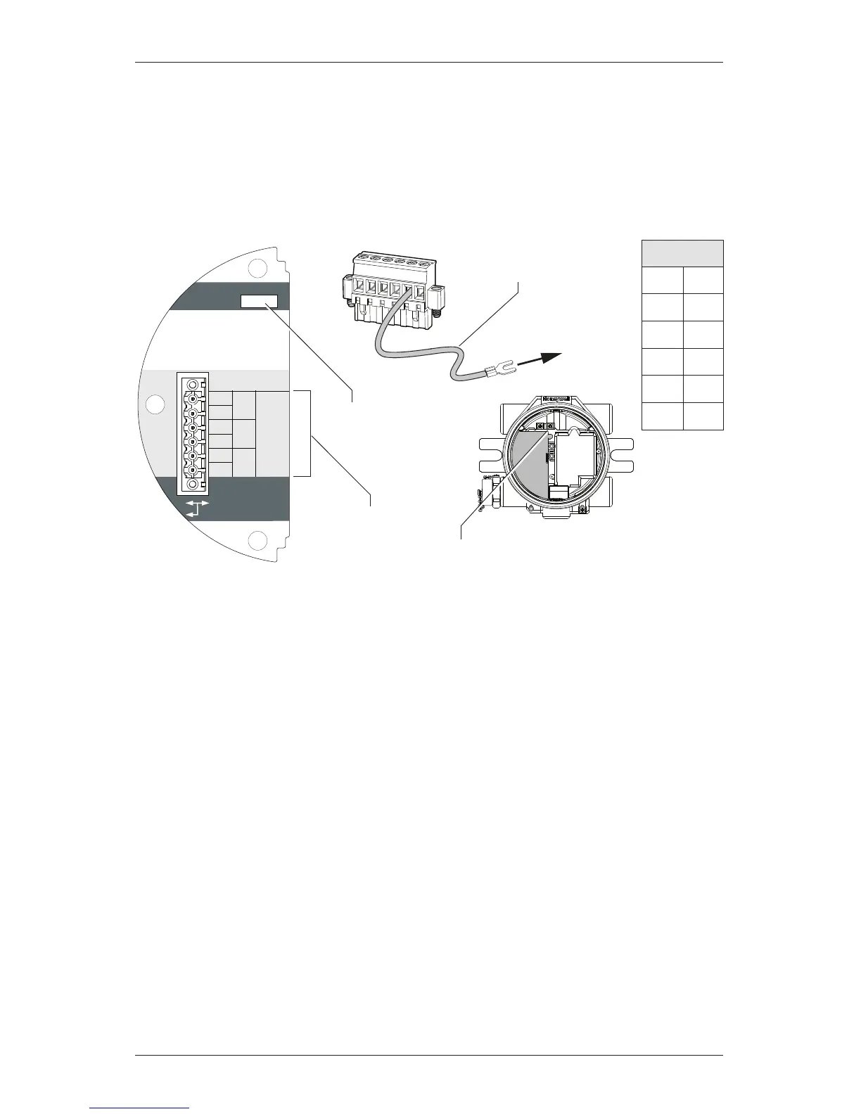
5.4 Foundation Fieldbus
Foundation Fieldbus connections to the XNX transmitter are made through a
pluggable terminal block on the Foundation Fieldbus option board, shown in
Figure 26. A simulation switch (SW5) is included on the board to enable/disable
simulation mode. Terminals 3-1 through 3-4 are provided to facilitate bus wiring;
there is no internal connection to other XNX circuitry. Terminal 3-1 is connected
internally to 3-2. Similarly, terminal 3-3 is conneted internally to 3-4.
+
+
TB-3 Modbus
Use shorting jumper
supplied to maintain
connection during
service
S5 Sim Mode
Out
In
3-1
3-2
3-3
3-4
3-5
3-6
F+
F+
F-
F-
FS
FS
TB-3 FFB
Jumper
assignments
1
2
3
4
5
6
to internal
ground lug
SW5 -
Sim switch
Internal ground lug
Foundation Fieldbus
ground cable
Figure 26. Foundation Fieldbus option board, terminal block, and jumper switch
TB3
1 F+
2 F+
3 F-
4 F-
5 FS
6 FS

 Loading...


