XNX Universal Transmitter Quick Start Guide
17
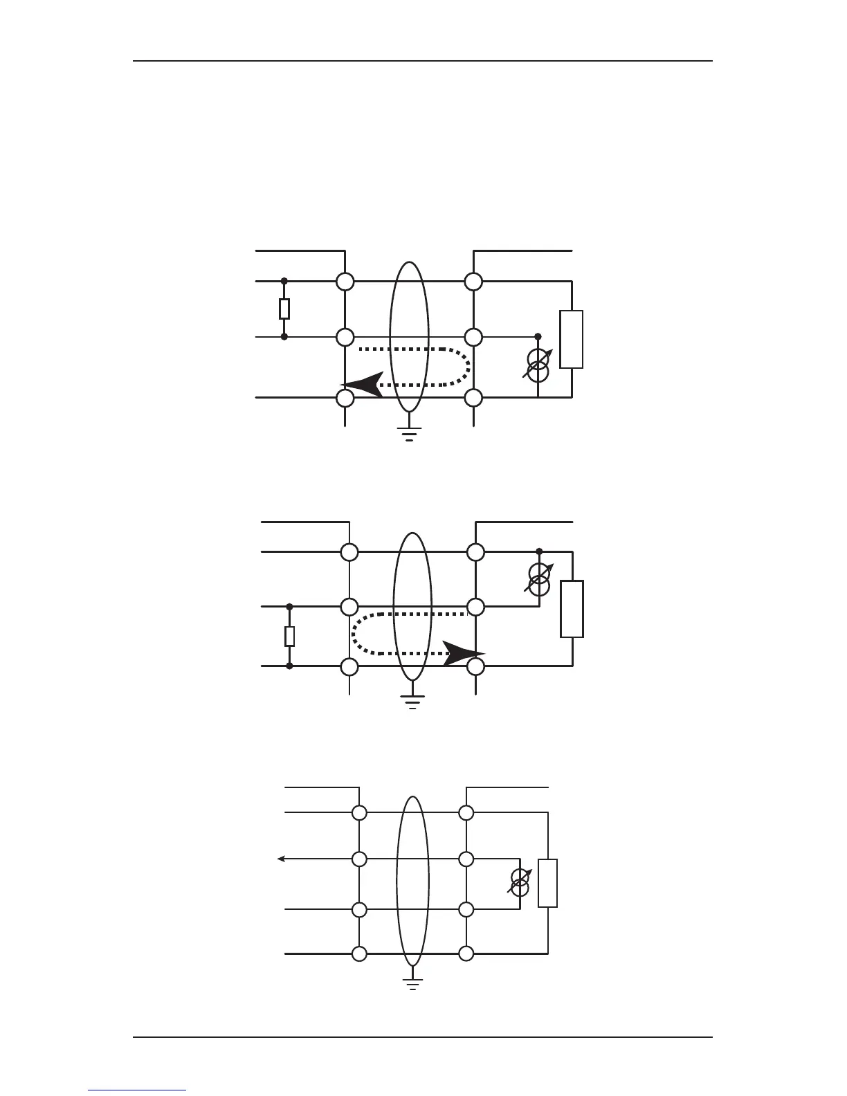
Power and 4-20mA connections are made at TB-1 and are identical for the EC,
IR, and mV personality boards. The minimum loop impedence is 200 ohms; the
maximum is 500 ohms when the transmitter is supplied with an input of 16 volts.
Failure to perform “Calibrate mA Output” or with loads outside the recommended
values may result in diagnostic warning or fault messages.
The total load resistance recommended for the 4-20mA output should be kept
lower than 500 ohms, including the resistance of the properly selected 4-20mA
cable and input impedance of the equipment to be connected.
Controller
+VE
Signal
-VE
R
L
1
2
3
1-1
1-5
1-3
+V
+mA
-V
XNX
Current
Flow
Figure 5. Sink wiring for XNX
XNX Source Configuration
Controller
+VE
Signal
-VE
R
L
1
2
3
1-1
1-6
1-3
+V
-mA
-V
XNX
Current
Flow
Terminate cable screen at the detector or controller, not both.
Figure 6. Source wiring for XNX
Controller
+V1
+V2
-V2
1-1
1-5
1-6
+V
+mA
-V
XNX
1-3
-mA
-V1
XNX Isolated Configuration
Figure 7. Isolated wiring for XNX

 Loading...


