
Do you have a question about the Honeywell XNX and is the answer not in the manual?
| Ingress Protection | IP66/67 |
|---|---|
| Product Type | Universal Transmitter |
| Enclosure Rating | IP66/67 |
| Display | LCD |
| Communication Protocols | HART, Modbus, Foundation Fieldbus |
| Power Supply | 24 VDC nominal, 18-32 VDC |
| Operating Temperature | -40°C to +65°C (-40°F to +149°F) |
| Material | Aluminum or Stainless Steel |
| Gas Types | Toxic, Oxygen, and Combustible gases |
| Output | 4-20 mA |
| Relays | 3 programmable relays |
| Approvals | ATEX, IECEx, UL, CSA |
| Sensor Compatibility | Electrochemical, catalytic, infrared, and other sensor types |
Details on how to mount the XNX Universal Transmitter using integral tabs or optional kits.
Guidelines for proper wiring, considering voltage drops, noise, and grounding.
Information on installation distances based on wire gauge and transmitter configuration.
Details on connections available on the POD for personality boards.
Configuration of 4-20mA output modes (Sink, Source, Isolated) and power connections.
Information on pluggable terminal blocks for customer connections.
Specific wiring instructions for EC personality boards.
Step-by-step guide for installing the plug-in EC sensor.
Procedure for remotely mounting the EC sensor using a kit.
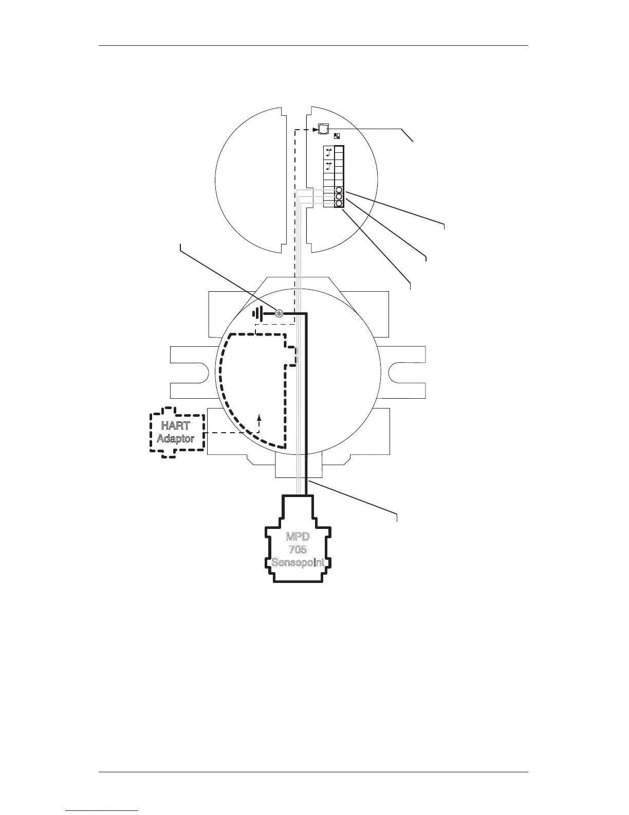
Wiring instructions for mV personality boards and connected sensors.
Guide for mounting mV sensors remotely from the transmitter.
Wiring instructions for IR personality boards and connected sensors.
Connecting IR sensors like Optima Plus or Searchline Excel to the XNX.


