Model
5315
A/ B
General
Informati
on
1-1.
INTRODUCTION
SECTION I
GENERAL
INFORMATION
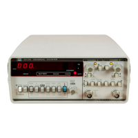
1-2. This manual provides information pertaining to
the
installation,
operation,
testing, adjust-
ments, and maintenance of
the
HP
Mode
l
53
1
5A
and 53158 Universal
Co
unters, shown
in
Figure 1-1.
1-
3.
This
manual is divided into eight sections, each covering a particular topic for
the
operating
and service of the
HP
Model
S31SA
/ 8. The top
ics
by
section
number
are:
Sedion
Topic
General
Information
II
Installation
lit
Operation
IV
Performance Tests
V Adjustments
VI Replaceable Parts
V
II
Manual Changes
VI r I Service
1-4. DESCRIPTION
1-5. The Hewlett-Packard Model
5315A
and 53158 are universal
co
unters, measuring signals
over a range from
0.1
Hz to
100
MHz.
Th
e
5315A
/ B measures
Fr
e
qu
ency, Period, Time Interval,
Time Interval Ave
ra
ge, Time Inter
val
Holdoff (Delay), and Ratio. A Totalize functi
on
with manual
or external gating is al
so
provided. A
ll
measurements except Totalize are displayed
in
engineer-
ing notation with up to eight digits of resolution.
1-6. Two
independent
input channels are prOVided for time interval measurements.
Each
input
channel has an attenuator
(Xl,
X20
), trigger slope sel
ecto
r, tr
igg
er
level/sensitiv
it
y control, and
ac-dc coupling. A switchable low-pass
fitter
on
Channe
l A and 3-state trigger lights are also
provided.
1-7. The
53
158
is
functionally identical to
the
53
1
5A.
The major differ
ence
is
that
the
53
15
B
is
designed for rack mounting or stacking and features a metal cabine t to minimize
EM!.
1-8. OPTIONS
1-9.
Th
e options
ava
il
able with the
5315A
/ 8
are
described
in
Table 1-1.
If
an
option
is
included
in
the
initial
order
, it
will
be
installed at
the
factory and ready for operation
upon
receipt.
If
an
option
is
ordered
for field installation,
it
w
ill
be
supplied
as
a retrofit kit. For field installation of
Option
001
and
002
, refer to paragraph 2-29.
1-10. SPECIFICATIONS
1-1
1.
Th
e inst
rument
specifications are listed
in
Table 1-1. Thesespecifications are
the
perform-
ance standards
or
limi
ts
aga
in
st
which
the
instrument may
be
tested.
1
-1

 Loading...