Model
531
5A/ B
Operatio
n
3-19. T.
I.
DELAY
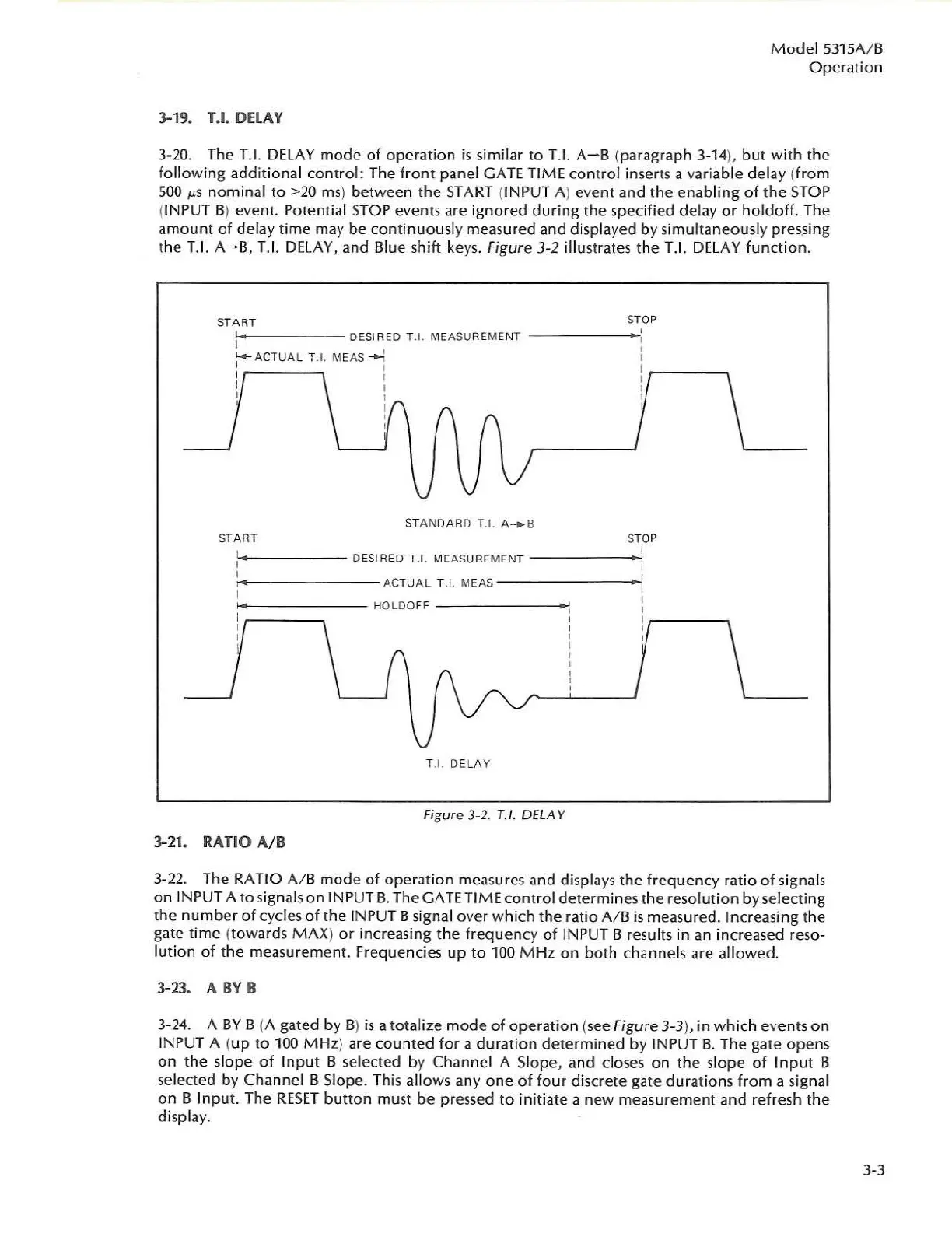
3-
20.
The
T.1.
DELAY
mode
of operat
ion
is
similar
to
T.
1.
A-B
(paragraph 3-14), but
with
the
follow
ing
addit
ional control:
Th
e fr
ont
panel GATE TI
ME
co
n
trol
inserts a variable
de
lay (from
500
J.lS
nom
inal
to
>20
ms
) between the START (INPUT A) event and the
enab
li
ng
of
the
STOP
(INPUT B) event.
Po
tential
STOP
events are i
gno
red du
ring
the
specified delay or
holdoff.
The
amount
of
delay time may be
conti
nu
ou
sl
y measured and di
sp
layed by s
im
ul
t
aneo
usly pr
es.sing
the
T.
1.
A-
B,
T.
r.
DElAY, and Blue shift keys. Figure 3-2 illu
st
rat
es
the
T.
I.
DELAY fu
nc
ti
on
.
START
STOP
,
MEASU
RE
ME
NT
,
DESI
RE
D T.!. ,
I
,
:-
ACTUAL
T.I. MEAS -...:
,
,
I
,
,
,
I
,
,
,
r
,
r.
"
\J
V
V
ST
ANDARD
TJ .
A
-.
S
ST
ART S
TOP
I
I
D
ES
IR
ED
T.
1.
MEASUREMENT
,
,
I
,
,
AC
TU
AL
T.I. MEAS
i
I
I
HO
LDO
FF
,
,
,
I
,
I
I
,
t
\
,
,
r.
,
,
,
(\;v
,
,
,
V
T.!.
DEL
A Y
Figure
3-2.
T.I.
DfLA
Y
3-21.
RATIO
AlB
3-
22.
T
he
RA
TI
O
AlB
mode
of
operati
on
meas
ur
es
and displays
the
freque
ncy
ratio
of
signals
on
INPUT A t
osign
al
s on INPUT
B.
The GATE TIME
cont
rol determines the resoluti
on
by selecting
the num
ber
of
cycles
of
the IN
PU
T B signal over w hich the
ra
t
io
AlB
is
measured. Increasing the
gate
tim
e (towards
MAX
)
or
in
creasing the
frequency
of
INPUT B resul
ts
in an
in
creased reso-
l
ut
ion
of
the measurement. Frequencies up
to
100
MHz
on
both channels are all
owed
.
3-23. A
BY
B
3-
24.
A
BY
B (A gated by B)
is
a totalize
mode
of
operation
(
see
Figure 3-3), in
whic
h events
on
INPUT A {
up
to
1
00
MHz
} are
coun
ted f
or
a dur
ation
de
te
rmined
by INPUT B. The gate
ope
ns
on the sl
ope
of
I
nput
B selected by Chan nel A Sl
ope,
and closes on the sl
ope
of
Input B
se
lected by Channel B Slope. This allows an
yone
of
fo
ur discrete gate
dura
tions
from
a sign
al
on
B I
nput.
T
he
RESET
bu
tton
must
be
pressed
to
initiate a
new
measurement and r
ef
resh
the
displ
ay.
).)

 Loading...


