EasyManuals Logo
Home>HP>Cash Counter>5315 A

HP 5315 A User Manual

HP 5315 A
103 pages
To Next Page IconTo Next Page
To Previous Page IconTo Previous Page
Page #29 background imageLoading...
Page #29 background image
o
o
.,
o
•
o
Model
5315A/8
Operation
STBY/ON. Suppl
ies
power
to
entire
machine in t
he
ON
positon. Supplies
powe
r
only
to
the Batt
ery-
Pa
ck (
Option
002
) in the S
TB
Y (Standby) pos
iti
on.
RESET
. Clears a
nd
updates display in
continuous
measurement modes, resets
counter
to
ze
ro
in totalize modes .
FREQ A.
Selects Frequency
mode
of
operation
(w
ith
Shift key
out
),
tor
signals
on
Input
A.
PER
A.
Selects Period
mode
of
operation
(w i
th
Shift key in
),
to
r signal
on
I
nput
A.
T.I.
A-B.
Selects Time Interval
mode
of
ope
r
ation
(
with
Shift key
out
) measuring
time
d
iff
eren
ces
from
Start signal
on
INPUT A
to
Stop signal
on
INPUT B {
when
in
SEP
I.
T.I. AVG A-
B.
Se
l
ech
Ti
me
Interval Average
mode
of
operation
(w i
th
Sh
i
ft
key
in
),
measuring
time
differences
from
Sta
rt signal
on
INPUT A
to
Stop signal
on
IN
PUT B
{
when
in
SEP
I .
T.
I.
DELAY. Selects Time Interval
mode
of
operation
(w i
th
Sh
ift key
out
), measuring
time
differences
from
Start signal
on
INPUT A
to
Stop signal
on
INPU
TB
(
whe
n
in
SEP
),
with
the
trigge
ring
of
the
Stop signal DELAYED (
he
ldotf
)
for
a
per
iod
of
time
determined
by GATE
TI
ME
DELAY
control.
CHECK.
App
li
es
10 M
Hz
f
rom
reference oscillator
to
MRC,
to
verify
operation
of
MRC,
display and GATE
TIM
E
control,
Microco
mpu
ter, etc.
RATIO
A/B.
Selects Ratio
mode
of
operation
(
with
S
hif
t key
out
), measuring
the
ra
tio
of
the signal
frequenc
y at INPUT A
to
the signal fr
equency
at INPUT
B.
A
BY
B.
Selects a
"gated
"
totalize
mode
of
operation
(
with
Shift key in), in
whic
h
the
signal
frequenc
y
of
INPUT A
is
totalized
for
a gate
duration
determined
by the s
ign
al
on
INPUT
B.
o
FREQ
C. Enables
the
Frequency C INPUT (
Option
(03
)
module
(
with
the
Sh
ift
key
out
).
GATE TIME.
Continuously
measures and displays
the
gate
tim
e
determined
by
the
GATE
TIME
cont
rol.
NOTE
T
he
trigge
r lights are disabled and extinguished w
hen
ei
ther
FREQ
C
or
GATE TIME is selected.
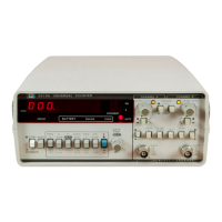
Figure
3-8. Front Panel Features
3-11

Table of Contents

Questions and Answers:

Question and Answer IconNeed help?

Do you have a question about the HP 5315 A and is the answer not in the manual?

HP 5315 A Specifications

General IconGeneral
BrandHP
Model5315 A
CategoryCash Counter
LanguageEnglish

Related product manuals