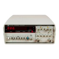
Model
53
1
5A
/ B
Service
8-8
A
cons
tant
2.5
volts from
the
ref
erence
regulat
or
US
is
input
to
oneside
of err
or
amp
lifier
U3.
The
ou
tput
of
the
+
5V
pass transistor
is
d
iv
i
ded
down
th
rough
vohage dividers
R19,
R16,
and
R
15and
input to
the
error amplifier. Any d
ri
ft
in
the
S·volt
out
is
dete
cted
and
co
rr
ected
by
U3
a
nd
Q4.
Q5
provides cu rr
ent
limit
in
g
to
=6 amps max
imum
. T
he
regulated +5 volls is
outp
ut
to
the
ins
tru·
men
t and
in
put to U4, the +3 volt regulator.
Th
e
ou
t
pu
t
of
t
hi
s regulator
is
set by vo
lt
age divider
R12,
R1
1,
and
feed back resistor R1
0.
C2
l filters t
he
+3
befo
re it
is
output
to the MRC.
8·48.
T
he
unregulated -9V
dc
is
applied to
the
-5.2V regulator
U6.
The
output
of
U6
is
set by
vollage divi
der
R23,
R22
,
and
feedb
a
ck
resistor
R2
l . C26 f
il
ters
the
-5.2
be
f
ore
it
is
output
to
the
in
put
amp
lifier assembly.
8·49.
U3
is used in conjunction wi
th
the
Battery·Pack, Option 002,
to
disable the main
power
supp
ly should the battery char
ge
level dr
op
to
a
point
less than
20
%
of
fu
ll
cha
rge.
8-50. A2 Display Assembly
8·51. The display assembly provides eight digits of resolu
ti
on
with
seven·segme
nt
LEOs
De
thr
oug
h
07.
The displays
are
controlled
by display driver
U3.
T
he
display driver
cont
ai
ns
complete
d
ecoding,
memor
y,
and scan circuitry as well as
power
drivers for
the
LEOs.
The
~x~
n e n
t
digit
is
decode
d
in
U2
and displayed in 058.
Ul
drives annunciators lights for
GA
TE
,
-
, H
z,
and
s.
8-52.
Al
I
np
ut Assemb
ly
8-
53.
Th
e I
nput
Assembly
co
ntains
th
e A
and
B
Channe
l signal conditio
ni
ng switches, the
Tr
igger Level/ Sensi
ti
vity
cont
rols,
and
Trigger
lig
hts. 51 and
510
select eith
er
AC
or
DC
coupling.
57
is
th
e
SEP
/
COM
A sw
it
ch which allows the Channel B ampl
if
i
er
to
be
driven by eith
er
the
B
Channel BNC
(2
) in
SEP
,
or
t
he
A Channel BNC
(J
l ) in
COM
A.
S3
and
58
select Xl or
X20
a
tten
uation by switching in (
or
out)
the
voltage d ividers Rl ,
R3
and
R1
4,
R12.
C4
,
C5
and C8,
C9
com
pensate
for hig h
freque
n
cy.
R
4,
R9,
C7
and
R1
6,
R
17
, Cl 0 form
current
limiting
ne
two
rk
s.
C
R1
, CR2 and CR3, CR4 are voltage
lim
it
ers.
S5
selects a
no
rmal
or
l
ow
pass
fi
lter configurati
on
for Channel
A.
In
the
low pass
mo
d
e,
C7
is
discon
nected
, and the Hi Frequ
ency
input on pin
13
is c
onn
ected
to
gro
und.
Th
e combinatio n
of
R9
, st
ra
y capa
ci
tan
ce
and
the
input capacitan
ce
of
the amplifier on
A4
roll off frequencies
above
100
kH
z.
8·54.
Th
e L
EVEl
/
SENS
cont
rols
R2
and
R15
provide
adjustable
dc
levels. from +
5V
to
-5.2V for
u
se
with eit
her
the
L
EVE
L
or
SE
NS
ITI
V
IT
Y
out
puts. With 54
or
S6
in
the
SENSITIVITY
positi
on,
t
he
voltage
swi
ng
is
applied
to
the
divi
der
n
etwo
r
ks
R6,
R5
,
R7
and
R10, R11,
R13
. providing a voltage
swing of =+40 to -
70
m
ill
ivolts
to
the Sensitivity
node
of
the
A4
comparato
rs. The L
EVEl
outpu
ts
default
to
effectively zero. With
the
switches set
to
T
RIGGE
R lEVEl, the
SENSITIV
I
TY
outputs
are
ti
ed
(high) to
+5V
and the vo
lt
age swing
is
divided in ha
lf
via resistor networks within
R8.
A
voltage swing
of
=-±l.5 vo lts
is
out
pu
t
to
the
Trigger L
eve
l inpu
ts
of
A4
comparato
r
s.
8·55. OSl and O
S2
are
the Channel A
and
Cha
nn
el B
Tr
igger
li
g
ht
s.
S2
and
S9
are t
he
slope
selection switches which
pull
to
gr
oun
d,
or
a
ll
ow
to
float h
ig
h,
the
Slope A a
nd
Sl
ope
B lines.
Th
ese lines are rout
ed
thr
oug
h
A4
to
the
microcompute
r
on
A
1.
8-56.
A4
Amplifier Assembly
8·57. T
he
Amplifier Assembly
co
ntains two essentially identical amplifi
er
ch
anne
l
s.
T
he
only
differ
ences
are; (1) the low
freque
ncy
and
high frequ
ency
am
plifiers have
separate
in
puts for
Channel A and are con
neded
together
f
or
Ch
annel
B.
(2) Channel B has
one
additi
ona
l
out
put
stage which d
ri
ves the
EXT
ARM
line. F
or
si
mp
li
ficati
on,
on
ly
Channel A
wi
ll
be
d
esc
rib
ed
.

 Loading...