Mo
del
53
1
5A
/ B
Operat
i
on
3-2
3-10. FREQ A
3
-11
.
Fre
quenc
y measurements are made by
connect
ing
a signal (
up
to
1
00
MHz
)
to
INPUT A,
and pressi ng
the
FREQ
A
function
key (with
the
Blue
sh
ift key
ou
t). Select the
appropriate
inp
ut
signal condi
tion
ing and adjust the LEVEl/ SENScont
rol
(with
TRI
GGER
LEVEl/SENSIT
IV
ITY key
to
TRIGGER L
EVE
L)
to
opt
i
mum
trigger
point.
The
opt
i
mum
trigger
poi
nt
may be
deter
min
ed by
centering
the
LE
V
El
/S
ENS
cont
rol
within the triggering range, indicated by the flashing trigger
light. The
GA
TE
TI
M E
con
trol
determin
es
the
resolut
ion
of
the measurem
ent,
and may be
displayed by p
ress
ing
the
GATE
TI
ME
func
ti
on
key and
Bl
ue shift key.
3-12.
PER
A
3
-1
3. The P
er
i
od
A
mode
allows
si
n
gle
per
io
d measurements
to
be made w
it
h periods of 105 s
to
10.0 nanoseconds in
to
IN
PUT
A. Select the
approp
riate
input
signal
condit
i
on
ing, and Trigger
l evel/Sensi
tiv
ity.
3-14.
T.
1.
A-B
3-15. T.I.
A-B
measures
the
time
inter
val be
tw
een a
STA
RT
signal
at
INPUT
Aa
nd a
STO
P signal
at
INPUT
B.
If b
ot
h the START and
STOP
signals are
derived
from
the same
sig
nal,
connect
the
sig
n
al
to
INPUT A and
set
the
SEP/COM A key
to
the
COM
A position (IN). Separate slope and
l evel/Sensitivity controls
for
each channel all
ow
variable triggering on eit
her
positive or
negative going slope. A single-shot ti
me
interval measurement may be made
over
a range of
100
ns
up
to
8 digits and 10
5
s after 9 digits.
3-16.
T.I. AVG
A-B
3
-1
7.
Th
e T.I. Average
mode
pro
vides greater resol
ut
ion
of
ti
me
interval m
eas
urement
s than
s
in
gle-s
hot
T.I.
mo
de
prov
ides. In the T.I. AVG
mode,
the
gate t
ime
control
varies the
numb
er
of
even
ts
of
time
in
ter
va
ls averaged (ap
pro
x
im
ately
GA
TE
TI
ME
X
REP
R
ATE
). The resol
ut
i
on
of
the
measurement
is
improved
by the
IN
, where N is
the
number
of
time
intervals averaged.
A
lim
ited range of negati
ve
T.I. measurements (Le., B triggers
befo
re A) are possi
ble
in
T.I.
AVe
mode.
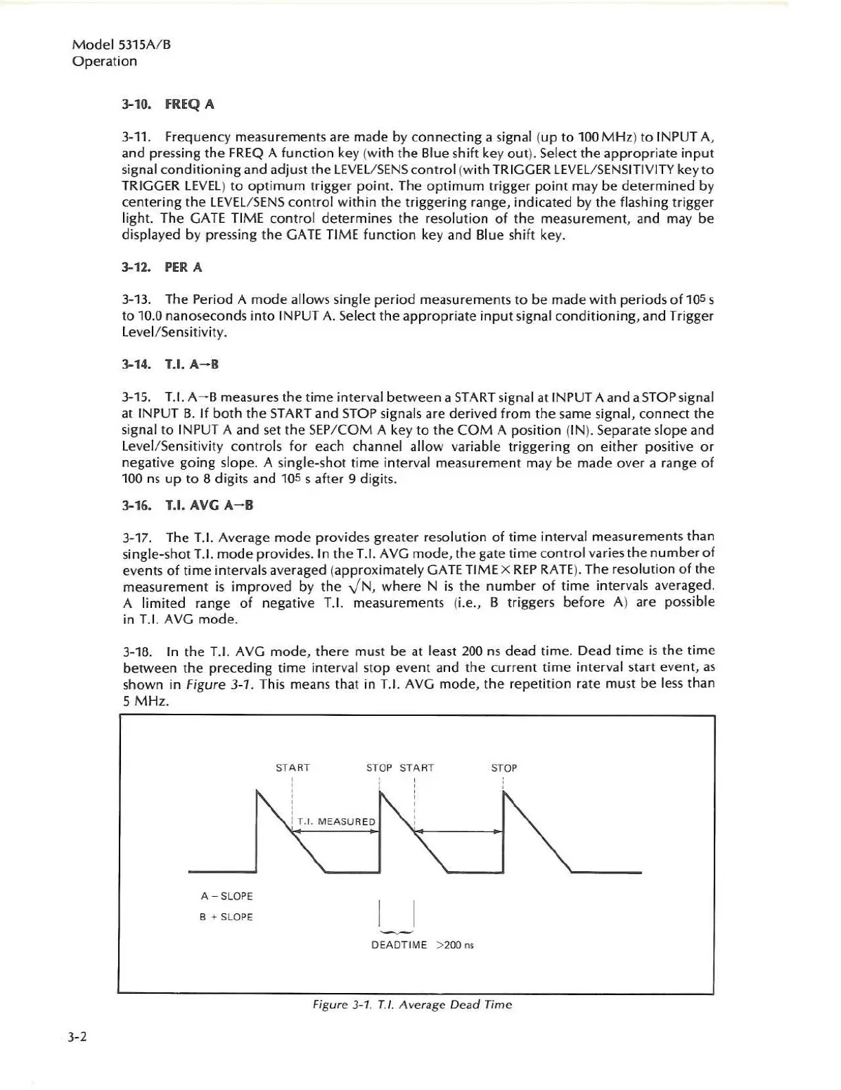
3-18.
In the T
.1.
Ave
mode,
there
mu
st
be
at
least 2
00
ns
de
ad
tim
e.
Dead ti
me
is
th
e ti
me
between
the
pr
eceding
time
interval stop event and the current
time
interval
sta
rt eve
nt
,
as
shown in Figure 3
-1
. This means that in
T.
1.
AVG
mode,
t
he
repeti
tion
rate must be l
ess
than
5 M H
z.
A -
SLOPE
B +
SLOPE
START
,
,
,
,
,
,
S
TOP
START
STO
P
:
T.1.
MEASU
RE
D
OEAOTIME > 200
ns
Figure 3-1.
n.
Average
Dead
Time
 Loading...


