Model
5315A
/8
Service
6-4
8-21.
SERVICE
AIDS
8-22. Pozidriv Screwd
riv
ers
8-23. Many screws
in
the
531S
A/B appear to be Phillips, but are not.
To
avoid damage to the
screw slot
s,
Pozidrive screwdrivers should
be
used.
8-24. Service Aids
on
Printed Circuit Boards
8-25. The servicing aids include test points, transistor and integrated circuit designations,
adjustment callouts, and assembly stock numbers.
8-26.
Assembly Identification
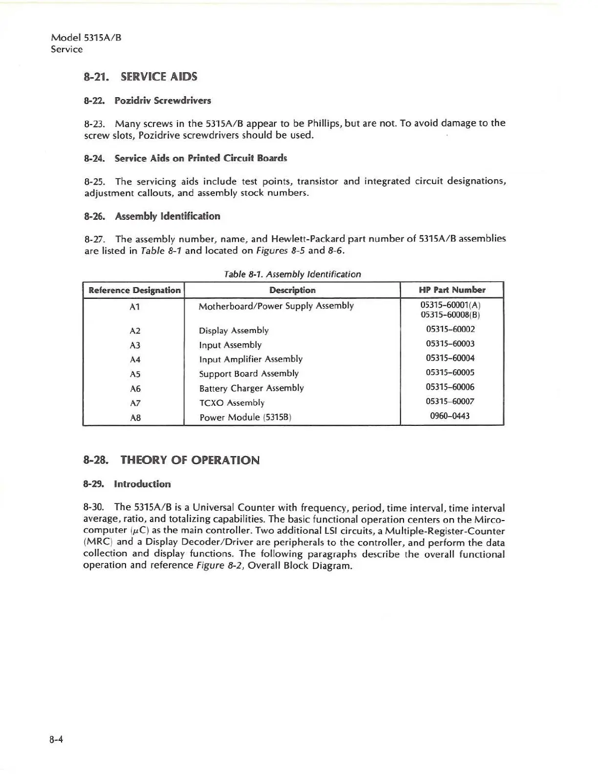
8-27. The assembly number, name, and Hewlett-Packard part
number
of 5315A/B assemblies
are listed in Table
8-1
and located
on
Figures 8-5 and 8-6.
Table
8 1 Assembly Identification
-
Refer
ence
Designation Description
HP
Part Number
Al
Motherboard/Power
Supply Assembly
OS315-60001{A
)
OS315
-
60008{B
)
A2
Display Assembly
05315-60002
A3
I
nput
Assembly
05315-60003
A4
Input Amplifier Assemb
ly
05315-60004
AS
Support Board Assembly
05315-60005
A6
Battery Charger Assembly
05315-60006
A7
TCXO Assembly
05315-60007
A6
Power
Module
(53158)
0960-0443
8-28. THEORY OF OPERATION
8-29. Introduction
8-30.
The
5315A
/ B
is
a
Un
iversal
Counter
with frequency, period, time
in
ter
va
l,
time interval
average, ratio, and totalizing capabilities. The basic functional operation centers
on
the
Mirco-
computer
(1lC)
as
the
main controller. Two additional lSI circuits. a Multiple-Register-Counter
(MRC) and a Display Decoder/ Driver are peripherals to
the
controller, and perform the data
collection and display functions. The folloWing paragraphs describe the
overall functional
operation and reference
Figure 8-2, Overa
ll
Block
Dia
gra
m.

 Loading...


